Engine gas distribution phase detection apparatus and method

A technology of gas distribution phase and detection device, which is applied in the direction of angle/taper measurement, etc., which can solve the problems of reducing assembly and production efficiency, affecting the normal operation of the detection process, and reducing detection accuracy, so as to improve assembly efficiency and production efficiency and save detection Process, the effect of improving detection accuracy

Inactive Publication Date: 2015-12-23
ANHUI JIANGHUAI AUTOMOBILE GRP CORP LTD
View PDF8 Cites 4 Cited by
  • Summary
  • Abstract
  • Description
  • Claims
  • Application Information

AI Technical Summary

Problems solved by technology

[0004] In the existing engine valve timing detection, the camshaft 104 can be driven to rotate only after the engine block assembly and the cylinder head assembly are combined, so the engine valve phase detection must combine the engine block assembly and the cylinder head However, during the phase detection process, if the engine valve timing does not meet the design value, it is necessary to disassemble the entire engine block assembly and cylinder head assembly, and then improve the camshaft 104 and its components. There are too many parts to be assembled and disassembled each time, which is time-consuming, reduces assembly and production efficiency, and increases costs; and because the engine block and cylinder head assembly are combined, the probe cannot directly touch the valve, and can only indirectly To detect the upper seat 107 of the valve spring, it is necessary to lengthen the probe, and the contact area between the probe and the upper seat of the valve spring 107 is too small, which will affect the detection accuracy and consistency of detection; The camshaft 104 interferes, which affects the normal progress of the entire detection process and reduces the detection accuracy

Method used


Image

  • Engine gas distribution phase detection apparatus and method
  • Engine gas distribution phase detection apparatus and method
  • Engine gas distribution phase detection apparatus and method

Examples


Embodiment Construction

[0036] In order to make the object, technical solution and advantages of the present invention clearer, the present invention will be further described in detail below in conjunction with the accompanying drawings and embodiments. It should be understood that the specific embodiments described here are only used to explain the present invention, not to limit the present invention.

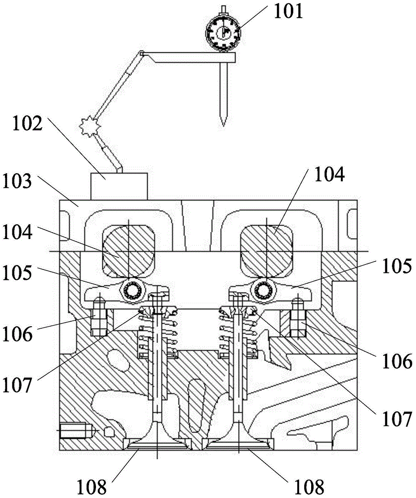
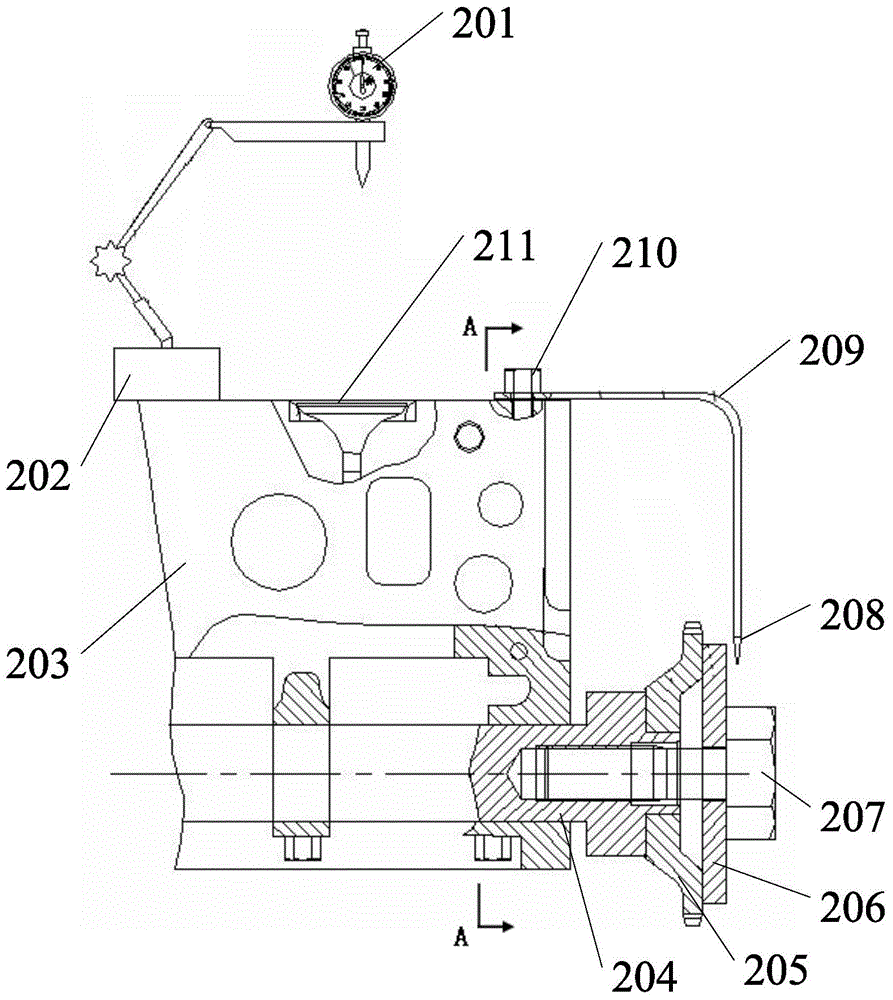
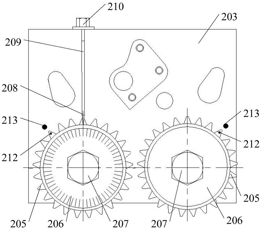
[0037] Please refer to Figure 2-Figure 4 , in a specific embodiment, the engine valve timing detection device provided by the present invention includes a dial indicator 201 and a pointer 208, the dial indicator 201 is installed on the side of the cylinder head 203 close to the valve 211, and the dial indicator The measuring head of 201 is perpendicular to the valve 211; the driving end of the camshaft 204 protruding from the cylinder head 203 is connected with a dial 206, and the driving end is connected with a driving mechanism 207 that drives the camshaft 204 to rotate around its axis; the poin...


PUM


Abstract

The invention belongs to the automobile part technology field and provides an engine gas distribution phase detection apparatus. The apparatus comprises a dial indicator and a pointer. The dial indicator is installed on one side of a cylinder cover, wherein the side is close to an air valve. A measuring head of the dial indicator vertically abuts against the air valve. A driving terminal of a camshaft, which is stretched out of the cylinder cover, is connected to a dial. The driving terminal is connected to a driving mechanism driving the camshaft to rotate about an axis. The pointer is installed on the cylinder cover and is extended to the dial along a radial direction of the dial. Through adding the driving mechanism, the driving terminal directly drives the camshaft to rotate so as to detect a lift maximum value and an air valve phase angle. By using the above structure, detection processes are saved. If the phase angle does not accord with a design requirement, only parts of a cylinder cover portion need to be dismounted. Working time is saved and assembling efficiency and production efficiency are increased.

Description

technical field [0001] The invention belongs to the technical field of automobile detection, and in particular relates to an engine valve phase detection device and method. Background technique [0002] The engine valve mechanism is an important part of the engine, generally composed of camshafts, rocker arms, analog tappets, valve guides, valves, valve springs and other components. The main function of the gas distribution mechanism is to open and close the intake valve and exhaust valve of each cylinder regularly according to the requirements of the engine working cycle and ignition sequence, so that the fresh charge can enter the cylinder in time, and the exhaust gas is discharged from the cylinder in time. And the sealing of the combustion is guaranteed during the expansion stroke. The opening and closing of the valve must have precise control, which is mainly related to the valve timing. There are two points to ensure the timing of the gas distribution: one is the des...

Claims


Application Information

Patent Timeline
Patent Type & Authority Applications(China)
IPC IPC(8): G01B5/24
Inventor 张来文刘凯郝加杰路建华余韶波贾昆明
Owner ANHUI JIANGHUAI AUTOMOBILE GRP CORP LTD
Why Eureka
Try Eureka