Ultrasonic flowmeter

A flowmeter and ultrasonic technology, applied in the field of fluid flow measurement equipment, can solve the problems of limited measurement range and low measurement accuracy of ultrasonic flowmeters, and achieve the effect of improving measurement accuracy and overcoming flow measurement errors

Active Publication Date: 2015-12-23
ZHEJIANG TIANXIN INSTR TECH CO LTD
View PDF6 Cites 2 Cited by
  • Summary
  • Abstract
  • Description
  • Claims
  • Application Information

AI Technical Summary

Problems solved by technology

[0008] Specifically, the technical problem to be solved by the present invention is to provide an ultrasonic flowmeter to solve the technical problems of the time-of-flight ultrasonic flowmeter with low measurement accuracy and wide measurement range.

Method used


Image

  • Ultrasonic flowmeter
  • Ultrasonic flowmeter
  • Ultrasonic flowmeter

Examples


Embodiment 1

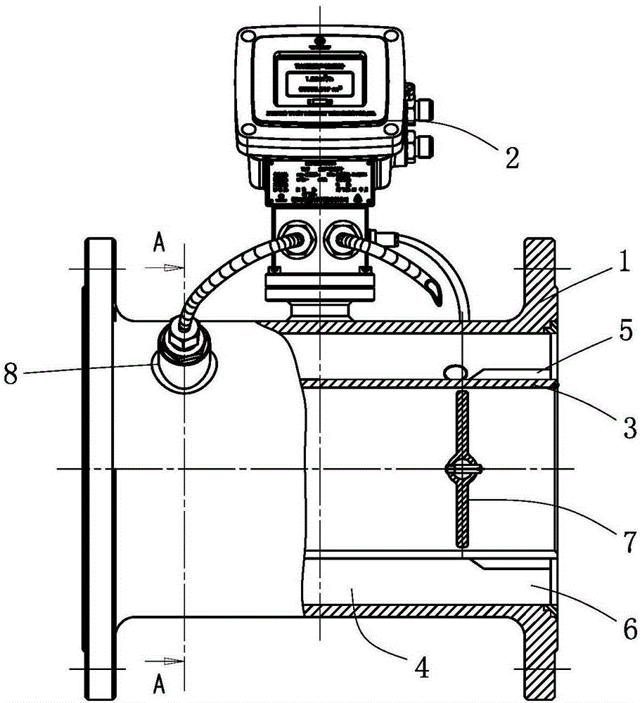
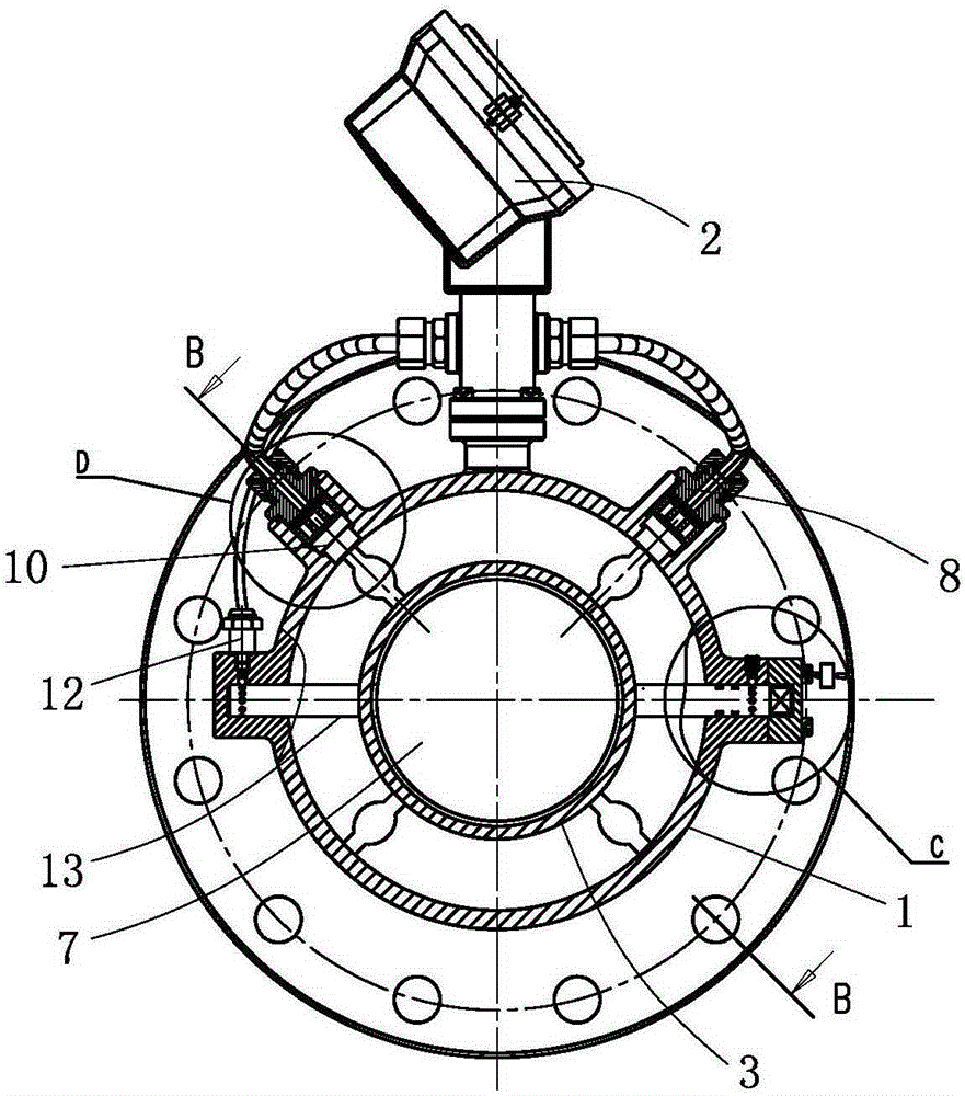
[0037] Such as Figure 1 to Figure 7 Commonly shown, the present invention discloses an ultrasonic flowmeter, which includes a cylindrical outer shell 1, a meter 2 is arranged outside the outer shell 1, and a control and conversion chip is arranged inside the meter 2, which are different from the traditional The principle is the same, so I won’t go into details here. The inner shell 1 is coaxially provided with the inner shell 3, and the inner shell 3 is also set as a linearly extending rotary structure. There is a communication between the outer shell 1 and the inner shell 3. The gap 4 and the circulation gap 4 are equidistantly arranged, and the two ends of the circulation gap 4 are respectively provided with a first reflection sheet 14 and a second reflection sheet 5, and the first reflection sheet 14 and the second reflection sheet 5 are cylindrical structures and are fixed on Between the outer shell 1 and the inner shell 3, the outer surfaces of the first reflective sheet...

Embodiment 2

[0043] Such as Figure 1 to Figure 7 Commonly shown, the present invention discloses an ultrasonic flowmeter, the structure of which is basically the same as that of Embodiment 1, the difference is that the ends of the first probe 8 and the second probe 9 are correspondingly provided for removing the attachment on the probe. The impurity removal device for impurities, the impurity removal device includes a sleeve 24 arranged in the flow gap 4, the cross-sectional shape of the sleeve 24 is shuttle-shaped, and the linear distance of the sleeve 24 in the fluid flow direction of the flow gap 4 is greater than that in the flow gap 4. The linear distance of the gap 4 perpendicular to the flow direction avoids the impact of the fluid and affects the measurement effect. One end of the sleeve 24 is open, and the other end is fixedly installed on the inner shell 3. The sleeve 24 is installed with a magnetic device sliding along the inside. The piston 25 and the end of the sleeve 24 near...

Embodiment 3

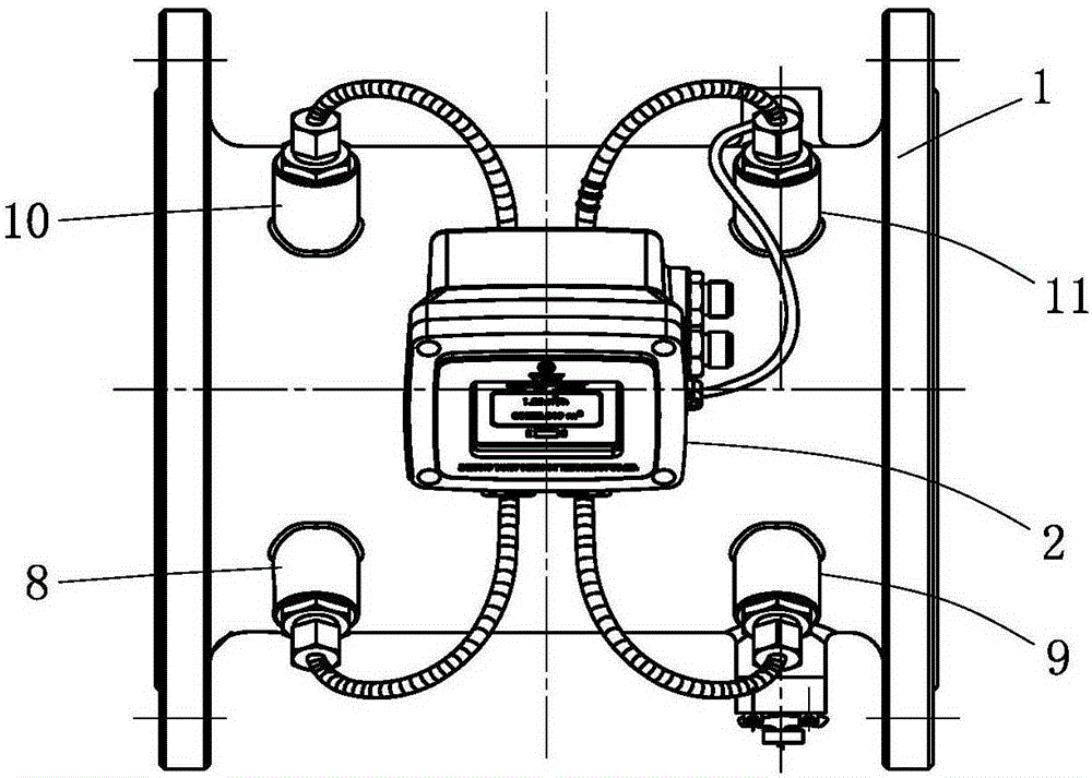
[0045] Such as Figure 1 to Figure 7 Commonly shown, the present invention discloses an ultrasonic flowmeter, the structure of which is basically the same as that of Embodiment 2, the difference being that a third probe 10 and a fourth probe 11 are installed at intervals on the outer shell 1, and the third probe 10 It is set on the same bus as the fourth probe 11 and the phase is staggered from the bus where the first probe 8 is located. As for the phase stagger angle, it is related to the diameter of the outer shell 1 and the measurement range. Those skilled in the art can set it according to professional knowledge. The third probe 10 is close to the first reflective sheet 14 and faces the first reflective slope 15 , the fourth probe 11 is close to the second reflective sheet 5 and faces the second reflective slope 16 , and both the third probe 10 and the fourth probe 11 are connected to the meter head 2 . The ends of the third probe 10 and the fourth probe 11 are respectivel...


PUM


Abstract

The invention discloses an ultrasonic flowmeter which belongs to the technical field of fluid flow measuring equipment. The flowmeter comprises an outer housing. A flowmeter head is arranged outside the outer housing. The inner part of the outer housing is coaxially provided with an inner housing. A flow gap is arranged between the outer housing and the inner housing. Two ends of the flow gap are respectively provided with a first reflector plate and a second reflector plate. The first reflector plate and the second reflector plate are respectively provided with flow channels which extend axially, wherein the number of the flow channels on the first reflector plate is same with that of the flow channels on the second reflector plate. The flow channels on the first reflector and the second reflector which are arranged oppositely are coaxially arranged. The end of the first reflector plate is provided with a first reflection oblique surface which is conically arranged. The end of the second reflector plate is provided with a second reflection oblique surface which is conically arranged. A first probe and a second probe are separately arranged on the outer housing. The first probe and the second probe are connected with the flowmeter head. The ultrasonic flowmeter overcomes technical problems of low measurement precision and no wide enough measurement range in a time-difference-method ultrasonic flowmeter. The ultrasonic flowmeter provided by the invention can be widely applied in measurement for the flow speed of the fluid.

Description

technical field [0001] The invention relates to a flowmeter, more particularly to an ultrasonic flowmeter for a closed pipeline, which belongs to the technical field of fluid flow measurement equipment. Background technique [0002] Due to airtightness and opacity, the flow rate of the fluid in the closed pipeline cannot be known to the outside world. As the simplest measurement method, the flow rate of the fluid can usually be measured, and then the flow rate of the fluid can be calculated according to the diameter of the pipe. In this method, the common method is to use non-contact measurement, and the most common tool is ultrasonic flow meter. [0003] The basic working principle of the ultrasonic flowmeter is as follows: when the ultrasonic wave propagates in the flowing fluid, it carries the information of the fluid flow velocity. Therefore, the flow velocity of the fluid can be detected by the received ultrasonic wave, and then converted into a flow rate. In this met...

Claims


Application Information

Patent Timeline
Patent Type & Authority Applications(China)
IPC IPC(8): G01F1/66
Inventor 何相之王秋宏丁忠瓦
Owner ZHEJIANG TIANXIN INSTR TECH CO LTD
Why Eureka
Try Eureka