
Clamp for extension test of glass fiber tape for optical cable and testing method
A glass fiber tape and tensile testing technology, which is applied in the direction of measuring devices, instruments, scientific instruments, etc., can solve the problems that the glass fiber tape cannot be stretched and tested, and achieve the effect of increasing friction
Patent Information
- Authority / Receiving Office
- CN · China
- Patent Type
- Applications(China)
- Current Assignee / Owner
- Publication Date
- 2015-12-23
- Estimated Expiration
- Not applicable · inactive patent
Smart Images
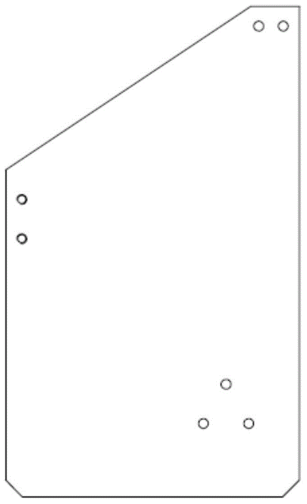
Figure 1 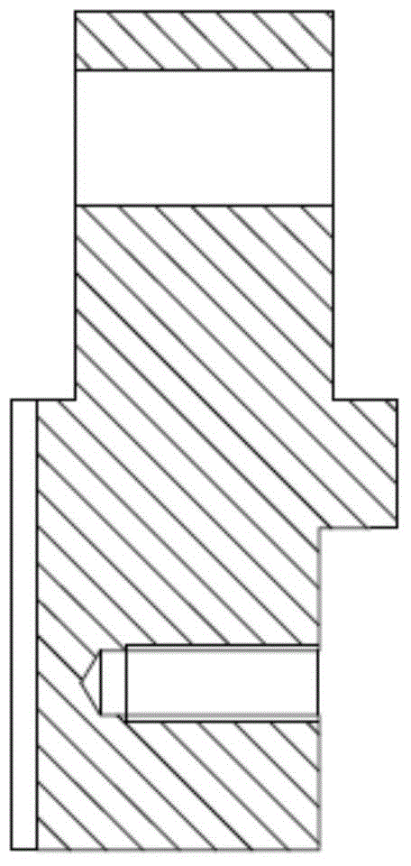
Figure 2 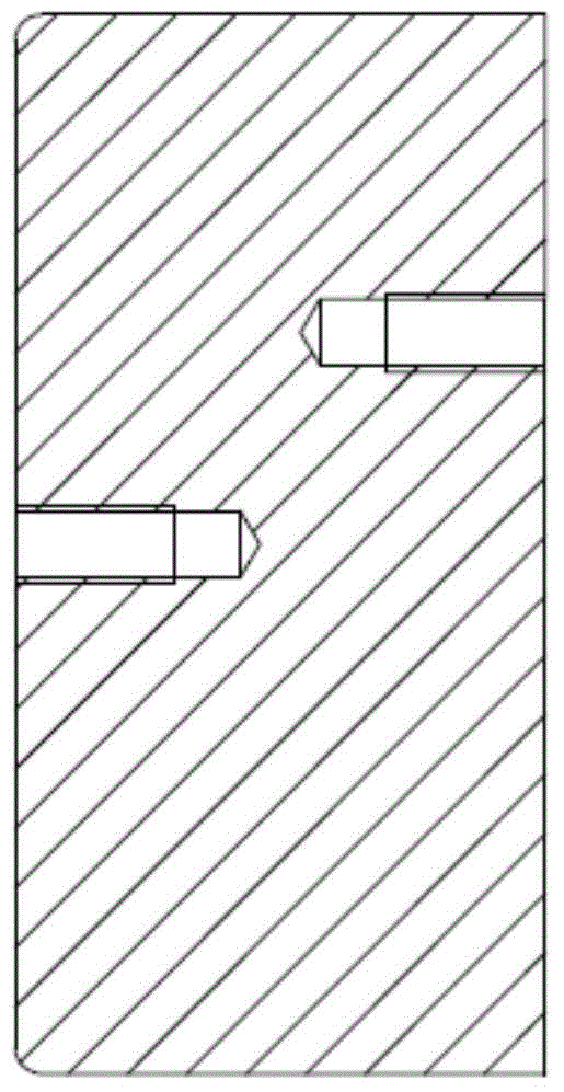
Figure 3
Abstract
Description
technical field
[0001] The invention relates to a device and a method for testing the tensile performance of ribbons, in particular to a fixture and a testing method for tensile testing applicable to glass fiber ribbons for optical cables. Background technique
[0002] The tensile test of materials is one of the most common methods in the testing of mechanical properties of materials. The stages of elastic deformation, plastic deformation and fracture in the test truly reflect the whole process of the material resisting external force. Although the success of a tensile test depends on many factors, the grips are one of the most basic and important pieces of equipment.
[0003] At present, two clamps are generally required to fix the two ends of the test material respectively during the tensile test. Among them, the upper fixture is used to fix the data sensor, and the lower fixture is used to fix the machine base. The sample is placed vertically between the two fixtures, a...
Examples
Embodiment Construction
[0036] The present invention is a kind of jig for tensile test of glass fiber ribbon for optical cable, refer to Figure 1 to Figure 7 , which specifically includes a base plate 1, the upper side of the base plate 1 is fixedly equipped with a cylindrical hole fixing head 2, and the lower side is fixedly equipped with a ring 3 and a fixed disc 4, and it is also fixedly installed on the edge of the middle plate. Clamping fixture 5 and I-type clamping device 6.
[0037] Among them, the bottom plate 1 is made of No. 45 steel material, and has been quenched and tempered and surface quenched. There are several fixing holes on it. The position and size of the fixing holes must be accurate. Roughness needs to reach 1.6.
[0038] The fixed head 2 with a cylindrical hole is made of No. 45 steel material, and after quenching and tempering treatment, all acute angles are inverted into obtuse angles, deburred, and the surface roughness must reach 1.6. For the cylindrical head fixed with ...