Grid electrode driving circuit, driving method thereof and display panel

A gate drive circuit and gate technology are applied in the field of gate drive circuits and display panels of gate drive circuits, which can solve the problems of not easy to design a narrow frame, increase the frame size of a display device, etc., so as to reduce the space occupied , the effect of reducing the number of

Active Publication Date: 2015-12-23
BOE TECH GRP CO LTD +1
View PDF7 Cites 29 Cited by
  • Summary
  • Abstract
  • Description
  • Claims
  • Application Information

AI Technical Summary

Problems solved by technology

In the prior art design, each stage of the shift register includes a pull-down node potential generating unit, such a design will increase the size of the frame of the display device, and it is not easy to realize a narrow frame design

Method used


Image

  • Grid electrode driving circuit, driving method thereof and display panel
  • Grid electrode driving circuit, driving method thereof and display panel
  • Grid electrode driving circuit, driving method thereof and display panel

Examples


Embodiment Construction

[0025] The present invention will now be described more fully hereinafter with reference to the accompanying drawings, in which presently preferred embodiments of the invention are shown. This invention may, however, be embodied in many different forms and should not be construed as limited to the embodiments set forth herein; rather, these embodiments are provided for completeness and thoroughness, and to fully convey the scope of the invention to those skilled in the art.

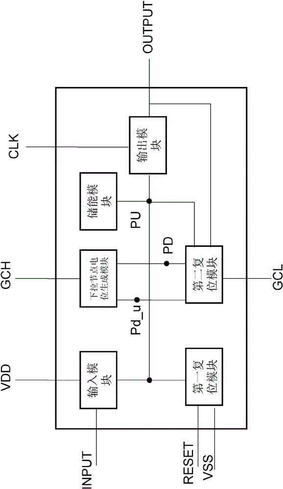
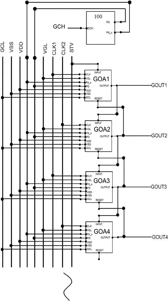
[0026] figure 1 A structural schematic diagram of a part of a gate driving circuit according to an embodiment of the present invention is illustrated. Such as figure 1 As shown, the gate drive circuit includes cascaded multi-stage shift registers GOA1, GOA2, GOA3, and GOA4, wherein the shift signal input terminal INPUT of the first-stage shift register GOA1 and the reset signal of the last-stage shift register The input terminal (not shown) is connected to the start signal line STV; the shift signal out...


PUM


Abstract

The invention provides a grid electrode driving circuit. The grid electrode driving circuit comprises cascaded shifting registers in multiple stages, wherein each shifting register comprises an input module, a first reset module, a second reset module, an energy storage module, an output module and a pull-down node potential generating module, and at least two shifting registers share one pull-down node potential generating module. The invention also provides a display panel comprising the grid electrode driving circuit and a method used for driving the grid electrode driving circuit.

Description

technical field [0001] The present invention generally relates to the field of display technology, and more particularly relates to a gate driving circuit, a driving method for the gate driving circuit, and a display panel including the gate driving circuit. Background technique [0002] With the development of display technology, the application of liquid crystal display devices is also becoming more and more extensive. A liquid crystal display generally includes a color filter substrate and an array substrate oppositely arranged, and a liquid crystal is arranged between the color filter substrate and the array substrate. Wherein, a source driving circuit and a gate driving circuit (GOA) are arranged on the array substrate, and both the source driving circuit and the gate driving circuit are located at the edge of the array substrate. Since the gate driving circuit is usually arranged at the edge of the array substrate, how to reduce the space occupied by the gate driving ...

Claims


Application Information

Patent Timeline
Patent Type & Authority Applications(China)
IPC IPC(8): G09G3/36
CPCG09G3/3677G09G2300/0408G09G2310/0286G11C19/28G09G3/36G09G2310/0283G09G2310/08G11C19/287H01L27/1214
Inventor 薛伟刘波李红敏宋萍
Owner BOE TECH GRP CO LTD
Why Eureka
Try Eureka