Magnetic monopole endfire antenna array

A magnetic monopole and end-fire antenna technology, which is applied to antenna arrays, antennas, antenna grounding devices, etc., can solve the problems affecting the aesthetics and concealment of the antenna, and the height of the large antenna, so as to improve the aesthetics and concealment, The effect of enhancing bandwidth and improving directionality

Active Publication Date: 2015-12-23
SYSU CMU SHUNDE INT JOINT RES INST +1
View PDF2 Cites 5 Cited by
  • Summary
  • Abstract
  • Description
  • Claims
  • Application Information

AI Technical Summary

Problems solved by technology

[0002] The existing end-fired antenna array achieves a polarization parallel to the plane where the antenna is located. If vertical polarization is to be provide

Method used


Image

  • Magnetic monopole endfire antenna array
  • Magnetic monopole endfire antenna array
  • Magnetic monopole endfire antenna array

Examples


Embodiment

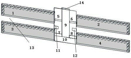
[0027] In the figure, 1-first magnetic monopole subunit, 2-second magnetic monopole subunit, 3-third magnetic monopole subunit, 4-fourth magnetic monopole subunit, 5-first microstrip transmission line , 6-second microstrip transmission line, 7-third microstrip transmission line, 8-fourth microstrip transmission line, 9-microstrip feeder, 10-floor, 11-first rectangular slot, 12-second rectangular slot, 13 - Dielectric plate, 14 - Excitation source.

[0028] Such as figure 1 As shown, a magnetic monopole end-fire antenna array includes four magnetic monopole subunits, respectively the first magnetic monopole subunit to the fourth magnetic monopole subunit 1-4, and four microstrip transmission lines, respectively These are the first to fourth microstrip transmission lines 5-8, microstrip feeder 9, floor 10, first and second rectangular slots 11, 12 and dielectric boards. Four magnetic monopole units, four microstrip transmission lines, microstrip feeders and floor printing are ...


PUM


Abstract

The invention provides a magnetic monopole endfire antenna array which has the advantages of low profile, wide frequency band and good directivity. The magnetic monopole endfire antenna array comprises an antenna unit, a microstrip transmission line, a microstrip feed line, a dielectric plate and a floor plate. The antenna unit, the microstrip transmission line, the microstrip feed line and the floor plate are printed and processed on the dielectric plate. The antenna unit comprises two pairs of magnetic monopole units which are symmetrically placed on both sides of the microstrip feed line to form two pairs of symmetrical array sources. Each magnetic monopole unit is connected with the microstrip feed line through the microstrip transmission line. The excitation source of the antenna array is radio frequency port excitation. Rectangular slits are symmetrically arranged on both sides of the floor plate. The antenna is flat, has the polarization characteristic of being perpendicular to the plane of the antenna, and has low application height. The aesthetics and the concealment of the antenna are improved. The magnetic monopole endfire antenna array has the advantages of wide frequency band and good directivity.

Description

technical field [0001] The present invention relates to the field of antennas, in particular to a magnetic monopole end-fire antenna array. Background technique [0002] Existing end-fire antenna arrays achieve polarization characteristics parallel to the plane where the antenna is located. If vertical polarization is to be provided, the antenna needs to be perpendicular to the floor, which occupies a large antenna height and seriously affects the aesthetics and concealment of the antenna. Contents of the invention [0003] The present invention provides a magnetic monopole end-fire antenna array to overcome at least one defect (deficiency) described in the above-mentioned prior art. Wide frequency bandwidth and good directivity. Most importantly, the antenna can realize the polarization characteristic perpendicular to the plane where the antenna is located. When the antenna is to provide vertical polarization characteristics, the antenna is in a flat state and has a ver...

Claims


Application Information

Patent Timeline
IPC IPC(8): H01Q1/38H01Q1/48H01Q1/50H01Q21/00
Inventor 尹涵梁志禧龙云亮李元新
Owner SYSU CMU SHUNDE INT JOINT RES INST
Why Eureka
Try Eureka