

Two-stage non-isolated full-bridge grid-connected inverter
A non-isolated, inverter technology, applied in the direction of converting AC power input to DC power output, output power conversion devices, electrical components, etc., can solve problems such as leakage current
- Summary
- Abstract
- Description
- Claims
- Application Information
AI Technical Summary
Problems solved by technology
Method used
Image

Examples
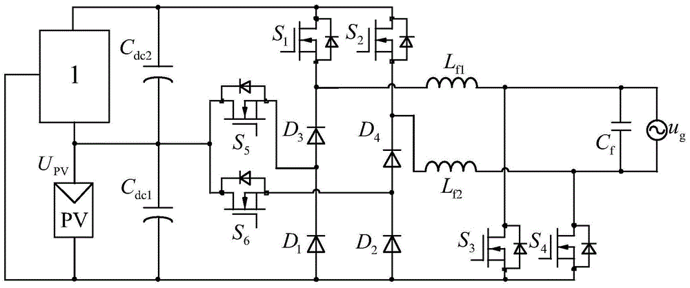
Embodiment 1
[0082] The two-stage non-isolated full-bridge grid-connected inverter described in Embodiment 1 includes six working modes:
[0083] Mode 1: The first power switch tube S 1 , the fourth power switch tube S 4 and the fifth power switch tube S 5 turn on, the other power switch tubes are off, and the incoming current flows through the first power switch tube in turn S 1 , the first filter inductor L f1 , power grid u g , the fourth power switch tube S 4 . third power diode D 3 The voltage stress for the second DC link capacitor C dc2 voltage value.
[0084] Mode 2: The fourth power switch tube S 4 and the fifth power switch tube S 5 turn on, the other power switch tubes are off, and the grid current flows through the fifth power switch tube in turn S 5 , the third power diode D 3 , the first filter inductor L f1 , power grid u g , the fourth power switch tube S 4 . first power diode D 1 The voltage stress for the first DC link capacitor C dc1 v...
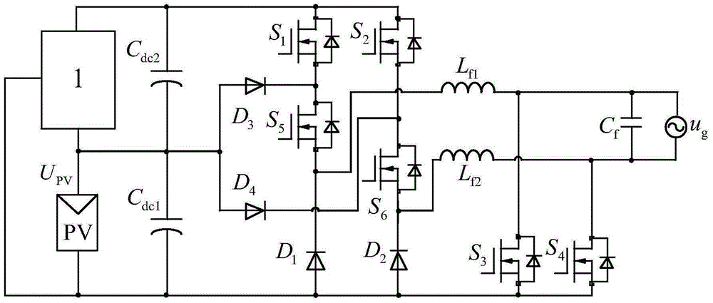
Embodiment 2
[0098] The two-stage non-isolated full-bridge grid-connected inverter described in Embodiment 2 includes six working modes:
[0099] Mode 1: The first power switch tube S 1 , the fourth power switch tube S 4 and the fifth power switch tube S 5 turn on, the other power switch tubes are off, and the incoming current flows through the first power switch tube in turn S 1 , the fifth power switch tube S 5 , the first filter inductor L f1 , power grid u g , the fourth power switch tube S 4 .
[0100] Mode 2: The fourth power switch tube S 4 and the fifth power switch tube S 5 is turned on, the other power switches are turned off, and the incoming current flows through the third power diode in turn D 3 , the fifth power switch tube S 5 , the first filter inductor L f1 , power grid u g , the fourth power switch tube S 4 ; The first power switch tube S 1 The voltage stress for the second DC link capacitor C dc2 voltage value.
[0101] Mode 3: The fourth...
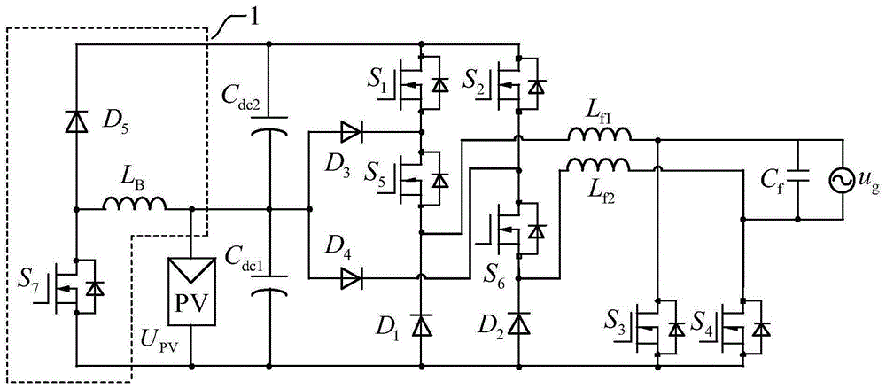
Embodiment 3
[0124] The two-stage non-isolated full-bridge grid-connected inverter described in Embodiment 3 includes six working modes:
[0125] Mode 1: The first power switch tube S 1 , the fourth power switch tube S 4 and the fifth power switch tube S 5 turn on, the other power switch tubes are off, and the grid current flows through the fourth power switch tube in turn S 4 , power grid u g , the first filter inductor L f1 , the first power switch tube S 1 .
[0126] Mode 2: The fourth power switch tube S 4 and the fifth power switch tube S 5 turn on, the other power switch tubes are off, and the grid current flows through the fourth power switch tube in turn S 4 , power grid u g , the first filter inductor L f1 , the third power diode D 3 , the fifth power switch tube S 5 .
[0127] Mode 3: The fourth power switch tube S 4 turn on, the other power switch tubes are off, and the grid current flows through the fourth power switch tube in turn S 4 , power gri...
PUM
 Abstract
Description
Claims
Application Information