
Reverse Extrusion Active Floating Die Forming System and Forming Process

A forming process and active technology, which is applied in the field of forging and forging in material processing engineering, can solve the problems of large temperature drop and poor forming force reduction effect, and achieve the purpose of reducing temperature drop, reducing changes in physical properties, and preventing strength reduction. Effect

Active Publication Date: 2018-06-26
NO 59 RES INST OF CHINA ORDNANCE IND +1
View PDF5 Cites 0 Cited by
  • Summary
  • Abstract
  • Description
  • Claims
  • Application Information

AI Technical Summary

Problems solved by technology

In this type of mold system, the die is connected to the spring. When the blank is punched by the punch, the blank is deformed, and part of the blank will move upward through the gap between the punch and the die. Under the action of friction, the die slowly Move upward and return to the original position after forming; while the die is driven by the blank and cannot actively move with the blank, most of the forming force of the blank still exists inside the blank, which has a poor effect on reducing the forming force. Without the feature of increasing the fluidity of the billet, the die moves with the billet, and there is a large friction between the die and the billet, which will cause a large temperature drop

Method used


Image

  • Reverse Extrusion Active Floating Die Forming System and Forming Process

Examples


Embodiment 1

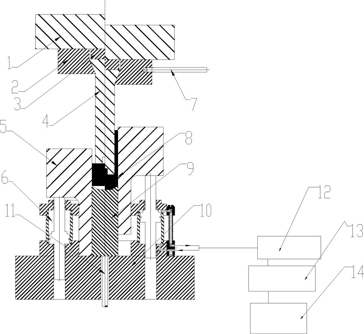
[0032] The first embodiment is basically as attached figure 1 Shown: a back-extrusion active floating die forming system, including an upper template 1 and a lower die pad 10. The lower die pad 10 is fixedly connected to the quick forging hydraulic press, the upper template 1 is set above the lower die pad 10, and the upper template 1. The upper mold fixing block 2 is welded underneath, the right side of the upper mold fixing block 2 is threadedly connected with a contact rod 7, an electromagnetic switch is provided under the contact rod 7, and a punch 4 is connected to the upper mold fixing block 2. The upper die gasket 3 is provided between the upper die fixing block 2 and the punch 4, the lower die gasket 10 is threadedly connected with an annular hydraulic cylinder 6, and the annular hydraulic cylinder 6 is fixedly connected with a concave mold 5, which is provided with Through the cavity of the die 5, the punch 4 is in clearance fit with the cavity. The cavity is slidably ...

Embodiment 2

[0040] The second embodiment: the difference from the first embodiment is that the moving speed of the die 5 is 5 times the upward moving speed of the blank 8;

[0041] The back-extrusion active floating die forming process includes the following steps:

[0042] (1) First use a heating tube to preheat the mold to 350°C;

[0043] (2) The blank 8 is continuously heated by an external induction heater to 1250℃;

[0044] (3) Set the speed of punch 4 to 40mm / s, the movement speed of annular hydraulic cylinder 6 to 200mm / s, and the speed ratio of punch 4 to die 5 to 1:5;

[0045] (5) After driving the upper mold plate 1 to move downwards, the upper mold plate 1 drives the upper mold fixing block 2 to move downwards, and the upper mold fixing block 2 drives the upper mold gasket 3 and the punch 4 to move downwards into the cavity. When the lower end of the punch 4 touches the blank 8 and presses it down by 10mm, the die core 9 supports the blank 8 and abuts against the blank 8, the contact ro...

Embodiment 3

[0046] The third embodiment: the difference from the first embodiment is that the moving speed of the die 5 is 0.5 times the upward moving speed of the blank 8;

[0047] The back-extrusion active floating die forming process includes the following steps:

[0048] (1) First use a heating tube to preheat the mold to 300°C;

[0049] (2) The blank 8 is continuously heated by an external induction heater to 1200°C;

[0050] (3) Set the speed of the punch 4 to 200mm / s, the movement speed of the annular hydraulic cylinder 6 to 100mm / s, and the speed ratio of the punch 4 to the die 5 to be 1:0.5;

[0051] (5) After driving the upper mold plate 1 to move downwards, the upper mold plate 1 drives the upper mold fixing block 2 to move downwards, and the upper mold fixing block 2 drives the upper mold gasket 3 and the punch 4 to move downwards into the cavity. When the lower end of the punch 4 touches the blank 8 and presses it down by 5mm, the die core 9 supports the blank 8 and abuts against the ...


PUM


Abstract

The invention relates to the field of the forging and forming of material processing engineering, and particularly discloses a backward-extrusion active floating concave mold forming system comprises an upper mold plate and a lower mold mat, wherein the lower mold mat is arranged on a rapid forging hydraulic machine, the upper mold plate is arranged above the lower mold mat, an upper mold fixing block is connected to one side, adjacent to the lower mold mat, of the upper mold plate, the upper mold fixing block is connected with a punch, a hydraulic cylinder is arranged at one side, adjacent to the upper mold plate, of the lower mold mat, the hydraulic cylinder is connected with a concave mold, a storage cavity penetrating through the concave mold is formed in the concave mold, the punch is in clearance fit with the storage cavity, a concave mold core is connected to the storage cavity in a sliding manner, the moving speed of the concave mold is 0.5 to 5 times of an upward moving speed of a blank, and then the operation of six steps are carried out to finally form the blank. Compared with the prior art, the moving speed of the concave mold can be positively controlled, the forming force can be reduced, and the mobility of the blank can be improved.

Description

Technical field [0001] The invention relates to the field of material processing engineering forging and forging forming, in particular to a back-extrusion active floating concave die forming system and forming process. Background technique [0002] Forging is the collective name of forging and stamping. It is a forming and processing method that uses the hammer, anvil, or punch of a forging machine to apply pressure to the blank through a die to cause it to be plastically deformed, so as to obtain a workpiece of the required shape and size. . [0003] In the forging process, the billet as a whole undergoes significant plastic deformation, and there is a relatively large amount of plastic flow; in the stamping process, the billet is formed by changing the spatial position of the area of ​​each part, and there is no large distance plastic flow inside. Forging is mainly used to process metal parts, but can also be used to process certain non-metals, such as engineering plastics, rub...

Claims


Application Information

Patent Timeline
Patent Type & Authority Patents(China)
IPC IPC(8): B21J13/02B21J5/02
CPCB21J5/02B21J13/02
Inventor 林军郭巨寿康凤陈强胡传凯赵祖德
Owner NO 59 RES INST OF CHINA ORDNANCE IND
Learn More