Electrolyte sealing device for tubular electrode electrolytic machining

A technology of tubular electrodes and sealing devices, which is applied in the field of electrolyte sealing devices, can solve problems such as difficult sealing of electrolytes, achieve the effects of improving processing accuracy and processing efficiency, and preventing lateral swinging

Inactive Publication Date: 2015-12-30
SHANDONG UNIV OF TECH
View PDF5 Cites 4 Cited by
  • Summary
  • Abstract
  • Description
  • Claims
  • Application Information

AI Technical Summary

Problems solved by technology

[0004] The invention provides an electrolyte sealing device for electrolytic processing of tubular electrodes, which

Method used


Image

  • Electrolyte sealing device for tubular electrode electrolytic machining
  • Electrolyte sealing device for tubular electrode electrolytic machining
  • Electrolyte sealing device for tubular electrode electrolytic machining

Examples


Embodiment Construction

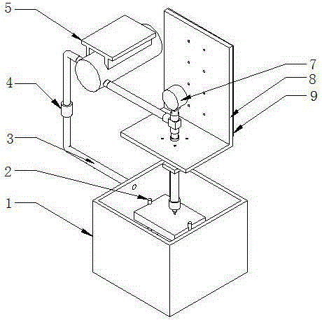
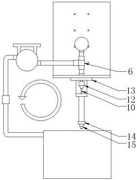
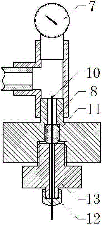
[0015] like figure 1 , 2 An electrolyte sealing device for tubular electrode electrolytic processing shown in and 3, which includes: electrolyte tank 1, workpiece fixture 2, pipeline 3, filter 4, high-pressure isolation pump 5, tee joint 6, pressure gauge 7 , Main body fixture one 8, insulating gasket 9, tubular electrode 10, water stopper 11, tubular electrode fixture 12, main body fixture two 13, guide fixture 14, guide 15.

[0016] like figure 1 , figure 2 , image 3 As shown, the pipeline 3 is connected to the liquid outlet of the electrolyte tank 1, and connected to the filter 4 and the high-pressure diaphragm pump 5 in sequence. The upward interface is connected to the pressure gauge 7. The pressure gauge 7 detects the working pressure of the electrolyte water outlet section in real time during the electrolytic processing, and the vertical downward interface is connected to the main body fixture 18. The main body fixture 18 has a groove for placing the water stopper...


PUM

PropertyMeasurementUnit
Diameteraaaaaaaaaa

Abstract

The invention provides an electrolyte sealing device for tubular electrode electrolytic machining. The electrolyte sealing device is characterized by comprising an electrolyte tank (1), a workpiece clamp (2), a pipeline (3), a filter (4), a high-pressure isolation pump (5), a three-way joint (6), a pressure gauge (7), a main body clamp I (8), an insulating pad (9), a tubular electrode (10), a water stop plug (11), a tubular electrode clamp (12), a main body clamp II (13), a guider clamp (14) and a guider (15). The water stop plug is used for sealing the device; the guider is used for preventing transverse swinging of a workpiece during machining; the insulating pad is used for insulating a motor; the tubular electrode clamp, the guider clamp, the workpiece clamp, the main body clamp I and the main body clamp II are respectively used for clamping and sealing fit of the tubular electrode, the guider and the workpiece; therefore, the clamping on the electrode, motor insulation and electrolyte sealing and circulation during tubular electrode electrolytic machining can be well realized.

Description

technical field [0001] The invention belongs to the technical field of electrolytic machining, in particular to an electrolyte sealing device for electrolytic machining of tubular electrodes. Background technique [0002] With the continuous advancement of the modernization process, high-tech products emerge in an endless stream, and there are more and more parts with small holes. Not only are the number of small holes on various components increasing and their diameters are getting smaller and smaller, but the precision and quality requirements for these holes are also getting higher and higher, which undoubtedly brings great challenges to processing technology. Various hole parts have high porosity, thin hole walls, large depth-to-diameter ratios, complex angle distribution, and high surface quality requirements. At the same time, many of these hole parts are made of high-hardness, high-strength heat-resistant materials. Difficult-to-machine materials such as steel, stain...

Claims


Application Information

Patent Timeline
IPC IPC(8): B23H3/10
CPCB23H3/10
Inventor 李志永路文文臧传武王钦强崔庆伟聂云聪
Owner SHANDONG UNIV OF TECH
Why Eureka
Try Eureka