Flexible welding line trolley positioning pin automatic switching equipment
What is Al technical title?
Al technical title is built by PatSnap Al team. It summarizes the technical point description of the patent document.
A technology of automatic switching and positioning pins, which is used in transportation and packaging, conveyor objects, conveyors, etc., can solve the problems of complex structure design, large space occupation, and difficulty in achieving consistent automatic programming of equipment installation accuracy. The effect of convenience, small footprint and reasonable design
Active Publication Date: 2017-12-26
上海奥特博格科技发展有限公司
View PDF5 Cites 0 Cited by
Summary
Abstract
Description
Claims
Application Information
AI Technical Summary
This helps you quickly interpret patents by identifying the three key elements:
Problems solved by technology
Method used
Benefits of technology
Problems solved by technology
[0002] At present, there are many positioning pin switching equipment for welding line trolleys related to domestic automobile factories. Usually, each set of trolleys is designed to have three-directional driving devices, but this structure design is very complicated, takes up a lot of space, and is difficult to achieve. Consistency of equipment installation accuracy and high requirements for automation programming
Method used
Image
Click on the blue label to locate the original text in one second.
Reading with bidirectional positioning of images and text.
Examples
Embodiment Construction
[0035] With reference to the drawings and preferred embodiments, the specific embodiments, structures, and features provided in accordance with the present invention are described in detail as follows:
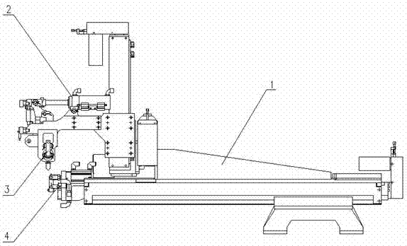
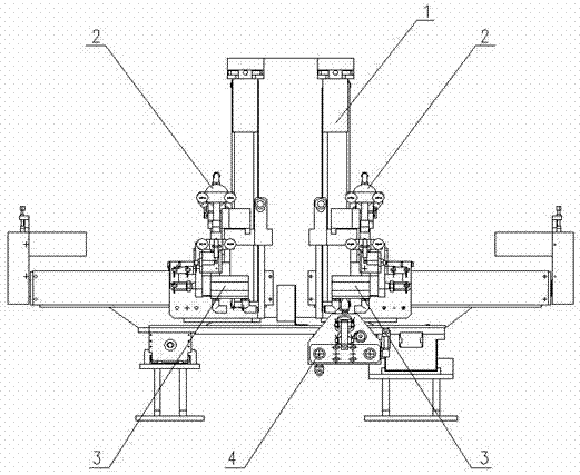
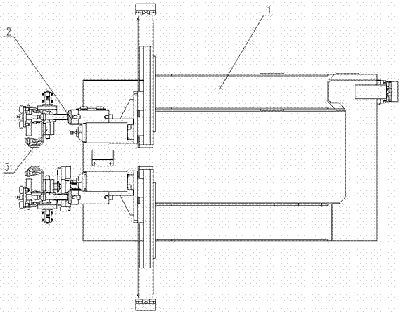
[0036] Such as Figure 1-Figure 15 As shown, a flexible welding line trolley positioning pin automatic switching equipment, the equipment is composed of driving assembly 1, H-hand grip assembly 2, B-hand grip assembly 3, T-hand grip assembly 4; Position the gripper assembly 2 with a positioning pin and install it to the drive assembly 1 through a threaded connection, position the gripper assembly 3 to the B direction and install it to the drive assembly 1 through a threaded connection, and install the gripper assembly 4 to the T with positioning pins. Locate and install to the drive assembly 1 through a threaded connection.
[0037] The drive assembly 1 includes a T-direction drive part 1-1 (T direction is the vehicle length direction), B-direction drive part 1-2 (B direction is t...
PUM
Abstract
The invention relates to automatic vehicle positioning pin switching equipment in a flexible welding line. The equipment is formed by connecting a driving assembly, H-direction gripper assemblies, B-direction gripper assemblies and a T-direction gripper assembly. The driving assembly comprises a T-direction driving component, B-direction driving components, H-direction driving components, a T-direction linear guide rail, a T-direction driving bracket A, a T-direction driving bracket B, a B-direction and H-direction driving bracket, a T-direction and B-direction driving bracket A, a T-direction and B-direction driving bracket B, a fixed connecting frame A, a fixed connecting frame B, a cover plate, a switch bracket and a ranging switch; each H-direction gripper assembly comprises a transition bracket, a cylinder mounting board I, a cylinder I, a limiting stopper and a pressing block; each B-direction gripper assembly comprises a cylinder II, a cylinder mounting board II a positioning plate I, a connecting rod I, a pressing header I and a swinging arm I; the T-direction gripper assembly comprises a cylinder III, a positioning plate II, a cylinder head, a swinging arm II, a connecting rod II, a pressing header II, a connecting frame and a breathing block. The automatic vehicle positioning pin switching equipment is simple in structure and reliable in performance, can switch a positioning pin position at will, and is high in speed and switching precision, and very significant in the application effect.
Description
Technical field [0001] The invention relates to a flexible welding line trolley positioning pin automatic switching equipment, in particular to a flexible welding line trolley positioning pin automatic switching equipment. Background technique [0002] At present, there are many domestic automobile factories related to welding line trolley positioning pin switching equipment, usually designed to have three-direction driving devices on each trolley, but this structure design is very complicated, takes up a large space, and is difficult to achieve Consistency of equipment installation accuracy and higher requirements for automated programming. [0003] Therefore, to provide an automatic switching device with simple structure, reliable performance, small space occupation, and capable of switching multiple trolleys is one of the problems that should be solved by those skilled in the art. Summary of the invention [0004] The purpose of the present invention is to overcome the above-men...
Claims
Application Information
Patent Timeline
Application Date:The date an application was filed.
Publication Date:The date a patent or application was officially published.
First Publication Date:The earliest publication date of a patent with the same application number.
Issue Date:Publication date of the patent grant document.
PCT Entry Date:The Entry date of PCT National Phase.
Estimated Expiry Date:The statutory expiry date of a patent right according to the Patent Law, and it is the longest term of protection that the patent right can achieve without the termination of the patent right due to other reasons(Term extension factor has been taken into account ).
Invalid Date:Actual expiry date is based on effective date or publication date of legal transaction data of invalid patent.