Container room with improved stand column structure

A container house and column technology, applied in the direction of columns, pier columns, pillars, etc., can solve the problems of poor thermal insulation and fire prevention performance, time-consuming and labor-intensive, and increased difficulty of assembly, so as to achieve strong compression resistance, increase thermal insulation effect, The effect of simplifying the assembly process

Inactive Publication Date: 2015-12-30
张家港市盛港绿色防火建材有限公司
View PDF7 Cites 2 Cited by
  • Summary
  • Abstract
  • Description
  • Claims
  • Application Information

AI Technical Summary

Problems solved by technology

However, the current assembly of container houses on site is time-consuming and labor-intensive. At present, most of the wall panels on each side of the container house are made separately and then welded sequentially. However, the overall strength of the container house assembled in this way is low and the safety is poor.
There are also some improved container houses with columns at the four corners of the side. The columns themselves are welded together with the wall panels, which can increase the overall stability of the container house, but this makes the installation process more complicated and increases the difficulty of assembly.
In addition, the panels of existing container houses are mostly made of steel plates, which have poor thermal insulation and fire protection performance, which not only greatly reduces the comfort of living, but also has low safety.

Method used


Image

  • Container room with improved stand column structure
  • Container room with improved stand column structure
  • Container room with improved stand column structure

Examples


Embodiment Construction

[0028] The technical solutions provided by the present invention will be described in detail below in conjunction with specific examples. It should be understood that the following specific embodiments are only used to illustrate the present invention and are not intended to limit the scope of the present invention.

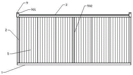
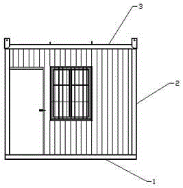
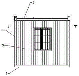
[0029] Please refer to the attached Figure 1 to Figure 5 , the container provided by the present invention includes a bottom frame 1, uprights 2 installed at the four corners of the bottom frame, and top struts 3 installed at the top of the uprights; A floor is installed on the bottom frame 1, a side plate 5 is installed between two adjacent columns 2, and a roof 6 is installed on the top pole 3. A door and a window are provided on the side plate for entering and exiting, ventilation and daylighting, and multiple windows can be opened. In the figure, the windows are respectively opened on the side plate 5 on one side of the door and on the other side side plate ...


PUM


Abstract

The invention discloses a container room with an improved stand column structure. The container room comprises a bottom framework, stand columns installed at the four corners of the bottom framework, and top supporting rods installed at the top ends of the stand columns. A floor is installed on the bottom framework. Side plates are installed between every two adjacent stand columns. A roof is installed on the top supporting rods. Each stand column is in a long-bar shape, the cross section of each stand column is in an L shape, an inserting groove is formed in the side face of each stand column, and two adjacent side plate ends are installed in each inserting groove. According to the container room with the improved stand column structure, a framework structure capable of being spliced is integrally adopted, the stand columns which are provided with the inserting grooves and are each of a stable structure are adopted, assembling is easy, the four side plates can be spliced and inserted into the stand columns through the structural design of the stand columns and can abut against one another through the stand columns and the side plates, the structure is steady and anti-pressure ability is high; in addition, each side plate is formed by splicing and inserting a plurality of fireproofing thermal insulation plates; through the design of male grooves and female grooves in the two sides of the plates, the assembling process is simplified, and cost is lowered; each fireproofing thermal insulation plate is of a three-layer structure, and good fireproofing thermal insulation performance is achieved.

Description

technical field [0001] The invention belongs to the technical field of container house structures, and in particular relates to a container house with an improved column structure. Background technique [0002] Container houses are easy to transport and reused in transit, so they are very popular as temporary houses for field and disaster relief. However, the current assembly of container houses on site is time-consuming and labor-intensive. At present, most of the wall panels on each side of container houses are made separately and then welded sequentially. However, the container houses assembled in this way have low overall strength and poor safety. There are also some improved container houses with columns at the four corners of the side. The columns themselves are welded to the wall panels, which can increase the overall stability of the container house, but this makes the installation process more complicated and increases the difficulty of assembly. In addition, the p...

Claims


Application Information

Patent Timeline
Patent Type & Authority Applications(China)
IPC IPC(8): E04H1/12E04B2/56E04B2/58E04C3/30E04C3/32E04C2/284E04C2/30E04C2/32E04C2/292
Inventor 葛庭洪
Owner 张家港市盛港绿色防火建材有限公司
Why Eureka
Try Eureka