Eureka AIR delivers breakthrough ideas for toughest innovation challenges, trusted by R&D personnel around the world.

Variable valve timing structure of motorcycle engine

A valve timing and engine technology, which is applied in the direction of engine components, machines/engines, mechanical equipment, etc., can solve the problems of small design space, low manufacturing cost, and difficult grafting of variable valve timing structures, so as to improve combustion efficiency, The effect of increasing the air intake

Active Publication Date: 2015-12-30
浙江美可达摩托车有限公司
View PDF7 Cites 0 Cited by
  • Summary
  • Abstract
  • Description
  • Claims
  • Application Information

AI Technical Summary

Problems solved by technology

If a fixed valve timing structure is used, it is difficult to achieve the best output torque characteristics and fuel economy characteristics of the engine at different speeds. The conventional method is to configure a specific motorcycle for common operating conditions. Valve timing phase, but when the motorcycle is used in other conditions, the torque performance and economic performance of the engine will be greatly reduced
At present, cars in the society are generally equipped with variable valve timing structures. However, due to the compact structure of motorcycle engines, small design space, and low manufacturing costs, it is difficult to graft the variable valve timing structures of automobiles to motorcycles.

Method used


Image

  • Variable valve timing structure of motorcycle engine
  • Variable valve timing structure of motorcycle engine
  • Variable valve timing structure of motorcycle engine

Examples


Embodiment Construction

[0025] The following are specific embodiments of the present invention and in conjunction with the accompanying drawings, the technical solutions of the present invention are further described, but the present invention is not limited to these embodiments.

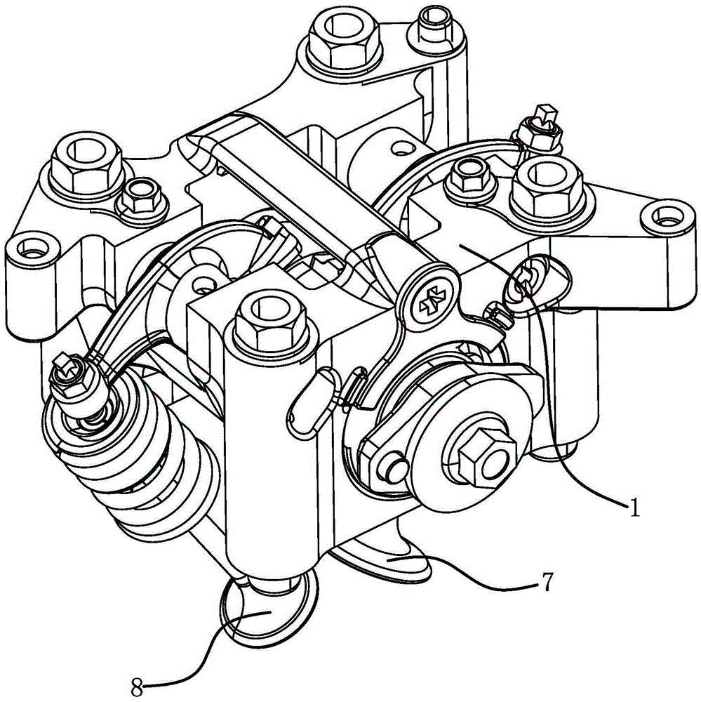
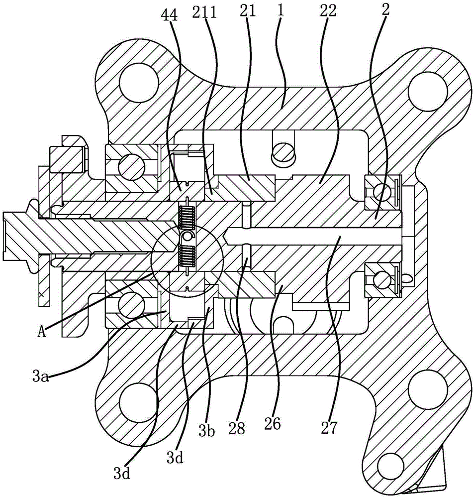
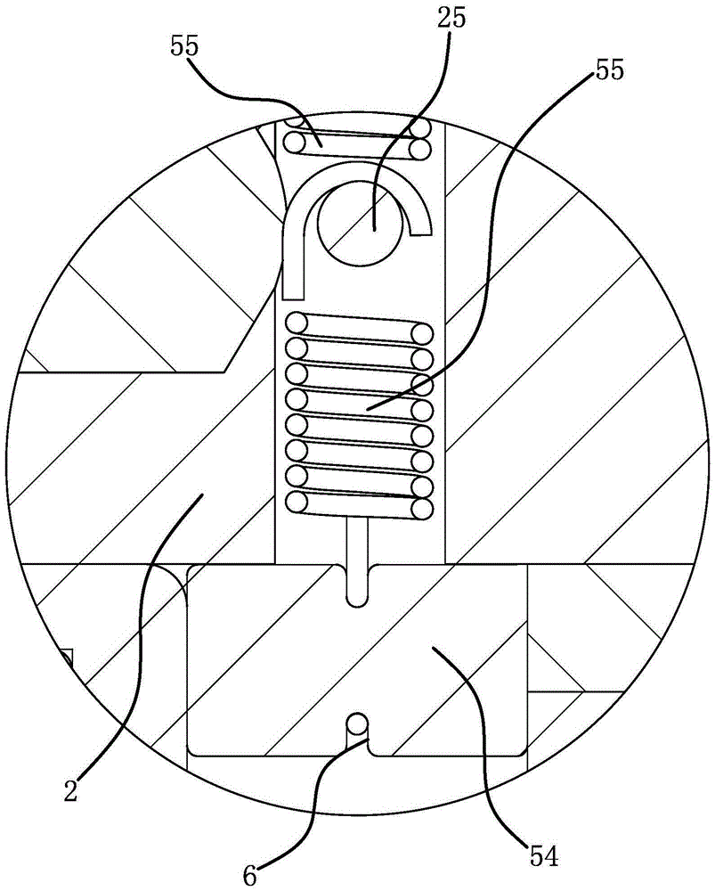
[0026] like figure 1 , figure 2 As shown, a variable valve timing structure of a motorcycle engine, the engine includes a cylinder block 1 and a camshaft 2 rotatably connected to the cylinder block 1, the camshaft 2 is fixedly connected with an exhaust cam 22, and the variable valve timing The timing structure includes an intake cam 21, a driving disc 3a and a driven disc 3b. The intake cam 21 is rotatably set on the camshaft 2, and the intake cam 21 is connected with the intake valve 7, and the exhaust cam 22 is connected with the exhaust valve. The door 8 is connected, the driving disc 3a and the driven disc 3b are provided with a central hole 3c, the driving disc 3a is fixedly sleeved on the camshaft 2, the driven dis...


PUM


Abstract

The invention provides a variable valve timing structure of a motorcycle engine, belongs to the technical field of motorcycle engines, and solves the problem that when the rotating speed of an existing motorcycle engine changes, the torque performance and economic performance of the engine are reduced. The variable valve timing structure of the motorcycle engine comprises a cylinder body and a camshaft, an exhaust cam is fixedly connected onto the camshaft, the variable valve timing structure comprises an admission cam, a driving disc and a driven disc, the admission cam sleeves the camshaft in a rotating manner, the driving disc fixedly sleeves the camshaft, the driven disc sleeves the camshaft in a rotating manner, a first transmission structure and a second transmission structure are arranged between the driving disc and the driven disc. The variable valve timing structure of the motorcycle engine can change valve timing through the rotating speed of the camshaft, so as to guarantee the air inflow of an air cylinder, and improve the combustion efficiency of the engine.

Description

technical field [0001] The invention belongs to the technical field of motorcycle engines, and relates to a variable valve timing structure of a motorcycle engine. Background technique [0002] The principle of engine variable valve timing technology is to adjust the intake (exhaust) amount, valve opening and closing time, and angle according to the operating conditions of the engine, so that the amount of air entering can reach the optimum value and improve combustion efficiency. The advantage is that it saves fuel and has a large power-to-liter ratio. The working speed range of a motorcycle is 1500-12000 rpm, and the working range is 2-3 times that of a car. If a fixed valve timing structure is used, it is difficult to achieve the best output torque characteristics and fuel economy characteristics of the engine at different speeds. The conventional method is to configure a specific motorcycle for common operating conditions. Valve timing phase, but when the motorcycle is...

Claims


Application Information

Patent Timeline
Patent Type & Authority Applications(China)
IPC IPC(8): F01L1/34
Inventor 吕浚潮邓定红龚建平张立成章玲莉
Owner 浙江美可达摩托车有限公司
Why Eureka
Eureka Blog
Learn More