Pipe fitting airtightness testing machine

A technology for air tightness testing and pipe fittings, which is applied in the direction of liquid tightness measurement using liquid/vacuum degree, and by measuring the increase and deceleration rate of fluid, etc., which can solve problems such as troublesome installation of pipe fittings, uneven end faces of pipe fittings, and misjudgment of quality. , to achieve a reasonable overall structure

Inactive Publication Date: 2015-12-30
宁波新合博园林机械有限公司
View PDF6 Cites 7 Cited by
  • Summary
  • Abstract
  • Description
  • Claims
  • Application Information

AI Technical Summary

Problems solved by technology

[0004] The above-mentioned test method has the following disadvantages: 1. The operation process is complicated, and the weight of the frame is relatively heavy. It is necessary to immerse the frame in water with the help of external equipment, and the installation of the pipe fittings is also relatively troublesome; 2. Use a jack to press down the plate to seal the pipe fittings And when the sealing ring is placed outside the two ends of the pipe fitting and clamped by the hydraulic cylinder to seal at both ends of the pipe fitting, the strength of both is difficult to control. If the forc

Method used


Image

  • Pipe fitting airtightness testing machine
  • Pipe fitting airtightness testing machine
  • Pipe fitting airtightness testing machine

Examples


Embodiment 1

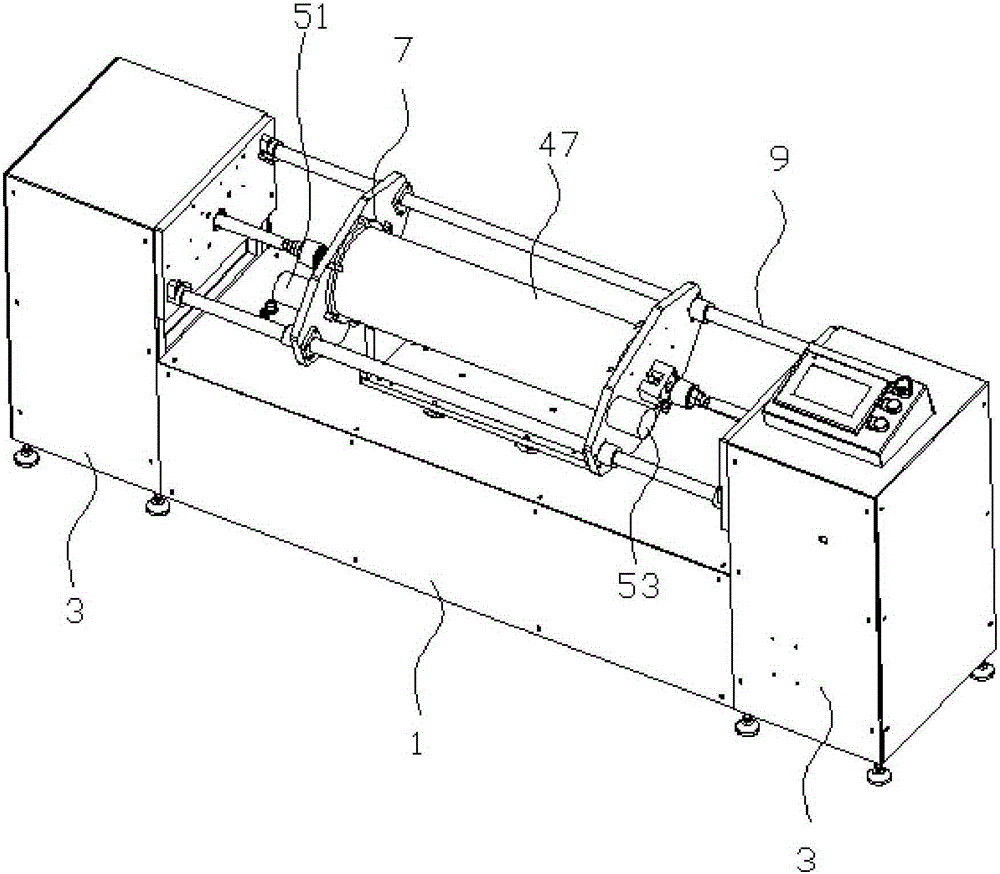
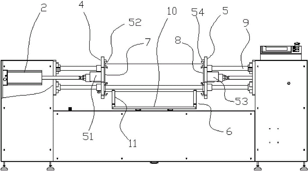
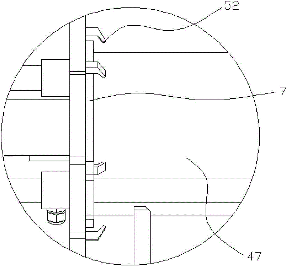
[0040] Example 1: Such as Figure 1 to Figure 5 In the illustrated embodiment, a pipe air tightness testing machine includes an air supply pump, an air pressure sensor 14, a main frame 1, two push plate cylinders 2, two side frames 3 with opposite inner sides, and a main end cover 4. , The secondary end cover 5, the main end cover and the secondary end cover are parallel to each other, the main frame is provided with a pipe supporting frame 6 for supporting the tested pipe, and two push plate cylinders are respectively arranged on the two side machines On the frame, the piston rod of one of the push plate cylinders is connected with the main end cover, and the piston rod of the other push plate cylinder is connected with the auxiliary end cover. The surface of the main end cover near the pipe support frame is provided for contact The main elastic sealing ring gasket 7 on the pipe end of the tested pipe is provided with a secondary elastic sealing ring plate 8 for contacting the ...

Embodiment 2

[0044] Example 2: Such as Figure 6 to Figure 8 In the illustrated embodiment, a pipe fitting air tightness testing machine includes an air supply pump 13, an air pressure sensor, a main frame, two push plate cylinders, two side frames with opposite inner sides, a primary end cover, and a secondary end cover , The main end cover and the auxiliary end cover are parallel to each other, the main frame is provided with a pipe fitting support frame for supporting the pipe under test, two push plate cylinders are respectively arranged on the two side frames, one of which pushes The piston rod of the plate cylinder is connected with the main end cover, and the piston rod of the other push plate cylinder is connected with the auxiliary end cover. The main end cover is provided with a main end cover for contacting the pipe end of the pipe under test on the surface near the pipe support frame. The elastic sealing ring gasket 7 is provided with a secondary elastic sealing ring plate 8 for ...

Embodiment 3

[0052] Embodiment 3: The basic structure and implementation of this embodiment are the same as those of Embodiment 2, and the difference lies in that: Figure 9 to Figure 12 Shown in the middle: It also includes two anti-return cylinders 31, one of which is fixed to the main end cover by an anti-return support 32, and the other anti-return cylinder is fixed to the secondary end cover by an anti-return support , The anti-return cylinder is provided with a push plate piston 33 that can slide up and down in the anti-return cylinder, and the push plate piston is connected to the inner end of a disc piston rod 34, and the outer end of the disc piston rod is provided There is a suction cup 35, the disc connecting piston rod is vertical, and the push plate piston divides the anti-return cylinder where it is located into an inflation chamber 36 and a movable chamber 37. The inflation chamber is connected to an anti-return air pipe 50 The airing end.

[0053] When the air pressure in the...


PUM


Abstract

The invention discloses a pipe fitting airtightness testing machine and aims at achieving the effects that the pipe fitting airtightness testing machine is convenient to operate, high in testing result accuracy and capable of guaranteeing that the two pipe ends of a pipe fitting are not prone to being damaged due to clamping. The machine comprises an air feed pump, a baroceptor, a main rack, two push plate air cylinders, two side racks, a main end cover and a subsidiary end cover, the two push plate air cylinders are arranged on the two side racks respectively, a piston rod of one of the push plate air cylinders is connected with the main end cover, a piston rod of the other push plate air cylinder is connected with the subsidiary end cover, a main elastic sealing ring pad is arranged on the main end cover, a subsidiary elastic sealing ring plate is arranged on the subsidiary end cover, and a main cover air hole is formed in the main end cover. The pipe fitting airtightness testing machine has the advantages that the pipe fitting can be positioned to the right position, the airtightness can be guaranteed, and the pipe fitting is not damaged due to clamping; the device is provided with a sealing structure which can be adjusted in a self-adaptation mode, and the airtightness effect in the high pressure testing process can be intensified; the machine is provided with an assistant positioning structure, the end covers can be prevented from moving backward, the push plate air cylinders can be protected, the sealing effect can be improved, and stability in the testing process can be maintained.

Description

Technical field [0001] The invention belongs to the technical field of pipe fitting air tightness testing, and particularly relates to a pipe fitting air tightness testing machine. Background technique [0002] Pipe fittings (pipes) of various materials are often used to transport various gases, liquids, and gas or liquid flowing in the pipe fittings. The pipe fittings have different sealing requirements when used in different occasions. Generally speaking, the pipe fittings with sealing requirements are Before leaving the factory, the leak tightness test is required, otherwise there will be greater safety risks. [0003] When testing pipe fittings in the prior art, gaskets or sealing rings are usually placed outside the two ends of the pipe fittings, and at the same time, a jack or hydraulic cylinder is used to clamp both ends of the pipe fittings, so that the sealing gasket or sealing ring and the pipe fittings are two The end (pipe end) forms a seal, and the entire sealed pipe ...

Claims


Application Information

Patent Timeline
IPC IPC(8): G01M3/28
Inventor 金建丰赵文敏
Owner 宁波新合博园林机械有限公司
Why Eureka
Try Eureka