
Optical bench for measuring focus length through magnification method

A technology of magnification method and optical bench, which is applied in the direction of testing optical performance, etc., can solve the problems of unsatisfactory high-precision measurement requirements, difficult correction of system errors, inconvenient measurement readings, etc., and achieve fast measurement speed, high precision, and realization The effect of automatic reading

Active Publication Date: 2015-12-30
MOONLIGHT (NANJING) INSTR CO LTD
View PDF8 Cites 8 Cited by
  • Summary
  • Abstract
  • Description
  • Claims
  • Application Information

AI Technical Summary

Problems solved by technology

But this method also has some disadvantages
For example, the system error is difficult to correct, and it needs to match the objective lens according to experience, which cannot meet some high-precision measurement requirements, the measurement reading is inconvenient, and the human interpretation error is large

Method used


Image

  • Optical bench for measuring focus length through magnification method
  • Optical bench for measuring focus length through magnification method

Examples


Embodiment Construction

[0017] Below in conjunction with specific embodiments, the present invention will be further illustrated, and it should be understood that these embodiments are only used to illustrate the present invention and not to limit the scope of the present invention. The modifications all fall within the scope defined by the appended claims of this application.

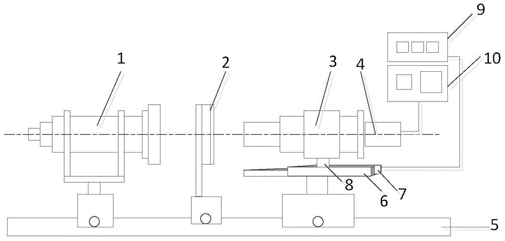
[0018] like figure 1 As shown in the figure, an optical bench for measuring focal length by a magnification method disclosed in an embodiment of the present invention includes a collimator light pipe assembly 1, a lens holder 2, a measuring microscope 3, and a CCD receiver 4 sequentially arranged on the main optical axis. , the Y-axis one-dimensional guide rail 5 parallel to the main optical axis, and the X-axis one-dimensional guide rail 6 perpendicular to the main optical axis, the X-axis one-dimensional guide rail 6 is provided with a slider 8, a lead screw (not shown in the figure) and high-precision grating ruler 7, the...


PUM


Abstract

The invention discloses an optical bench for measuring the focus length through a magnification method. The optical bench comprises a collimator assembly, a lens gripper and a measuring microscope which are sequentially arranged on a primary optical axis and a Y-axis one-dimensional guide rail parallel to the primary optical axis, and further comprises a CCD receiver and an X-axis one-dimensional guide rail perpendicular to the primary optical axis; the X-axis one-dimensional guide rail is provided with a sliding block, a lead screw for controlling the sliding block to move and a grating ruler for measuring the moving distance of the sliding block, and the measuring microscope is fixedly installed on the sliding block; the grating ruler is connected with a grating ruler data display instrument, and the CCD receiver is connected with an image display. According to the optical bench for measuring the focus length through the magnification method, by improving a traditional optical bench for measuring the focus length through the magnification method, the X-axis high-precision linear guide rail is additionally arranged, a double-image eyepiece is utilized for alignment, the focus length measuring error is decreased to 0.1%-0.5% from 0.5%-1%, and meanwhile the measuring range is widened and the measuring speed is increased.

Description

technical field [0001] The invention belongs to the technical field of optical instrument measurement, and in particular relates to a measurement device for measuring focal length by a magnification method. Background technique [0002] The characteristic parameters of the optical system are used as the basis for the design of optical instruments, and these characteristic parameters mainly determine the scope of application of the optical system. The focal length is an important characteristic of an optical system. As long as the focal length and the position of the focal point are known, all the information such as the position, size, upside-down and virtual reality of an object in any position can be completely determined by the optical system. Therefore, preparing to measure the focal length of an optical system is not only a means of accepting the product and checking whether it meets the design requirements, but also an important method to discover or find out the probl...

Claims


Application Information

Patent Timeline
Patent Type & Authority Applications(China)
IPC IPC(8): G01M11/02
Inventor 张斌
Owner MOONLIGHT (NANJING) INSTR CO LTD
Learn More