Road material washing test device adopting electromagnetic driving

A technology of scour test and road material, which is applied in the direction of testing wear resistance, etc., can solve problems that affect the life and use of the road surface, subsidence, road area mud, etc., and achieve the effect of being suitable for popularization, improving scour efficiency, and easy handling

Inactive Publication Date: 2015-12-30
CHANGAN UNIV
View PDF8 Cites 10 Cited by
  • Summary
  • Abstract
  • Description
  • Claims
  • Application Information

AI Technical Summary

Problems solved by technology

A large number of engineering practices have shown that the erosion of the grassroots often causes diseases such as mud accumulation, subsidence, cracking, and misplacement of the pavement, which seriously affect the life and use of the pavement.
[0003] Common equipment for evaluating the scouring performance of road materials at home and abroad mainly include rotating brushes and vibrating tables. This type of test equipment does not have the participation of water, which is quite different from the actual situation of the project; the road material scouring machine has the participation of water in the process of scouring , but this type of equipment cannot control the size and frequency of dynamic water pressure; test equipment such as jet high-pressure scouring and rotating water scouring can control the size of dynamic water pressure, but cannot simulate the pumping effect of free water, and cannot simulate road materials well The actual scouring situation; MTS base material scour equipment can well control the magnitude and frequency of dynamic water pressure, and can well simulate the scour effect of dynamic water on the base, but this type of equipment is bulky, costly and complicated to operate , not suitable for promotional use

Method used


Image

  • Road material washing test device adopting electromagnetic driving
  • Road material washing test device adopting electromagnetic driving
  • Road material washing test device adopting electromagnetic driving

Examples


Embodiment Construction

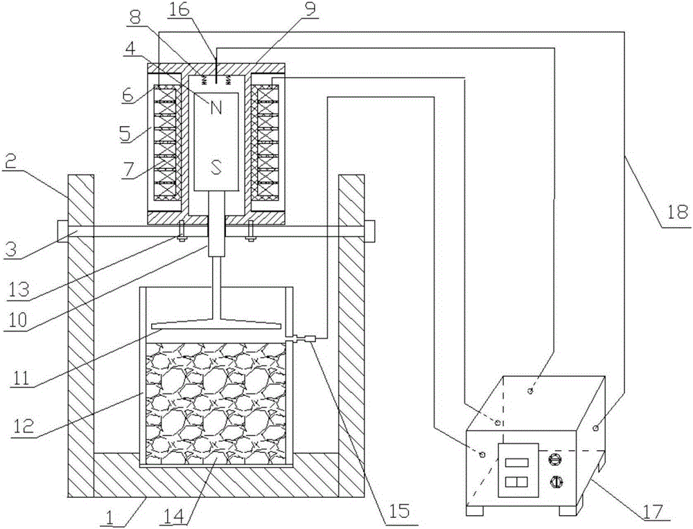
[0025] The water damage faced by road materials in the actual application process is mainly reflected in the erosion of the surface of the material by the water flow and the peeling off of the surface of the material due to the pumping action generated during the movement of the water flow. However, none of the existing test equipment can simulate the above process objectively and effectively. The idea of ​​the present invention is to provide a test device for simulating the effects of scouring, pumping and the like by controlling the movement of water flow.

[0026] like figure 1 As shown, an electromagnetically driven road material scouring test device includes a scouring bucket 12, a test piece 14 is placed in the scouring bucket 12, and water is filled in the scouring bucket 12, and the water surface exceeds the top surface of the test piece 14; A scour plate 11 that can move close to or away from the top surface of the test piece 14 is arranged above the top of the test ...


PUM

PropertyMeasurementUnit
angleaaaaaaaaaa

Abstract

The invention discloses a road material washing test device adopting electromagnetic driving. The device comprises a washing barrel, wherein a test piece is placed in the washing barrel, the washing barrel is filled with water, and the water surface is higher than the top surface of the test piece; a washing plate capable of moving towards or away from the top surface of the test piece is arranged above the test piece, the washing plate reciprocates to drive water flow to move, and the water flow moves to wash the surface of the test piece. According to the device, alternating current is introduced, the direction of the alternating current changes periodically, so that a guide rod reciprocates up and down and drives the washing plate to move, and dynamic water is produced in the washing barrel to realize the washing and suction circulating effect on the test piece; the frequency and the magnitude of the alternating current are changed by a control console, the pressure of the dynamic washing water can be controlled precisely, and washing of a base layer or a surface layer under conditions of different dynamic water pressure and acting frequency during actual washing can be simulated more truly.

Description

technical field [0001] The invention relates to the technical field of road engineering, and relates to a road performance test device, in particular to an electromagnetically driven road material scouring test device. Background technique [0002] Cement pavement and asphalt pavement are directly exposed to the natural environment. In rainy days or when there is water on the road surface, high-speed vehicles will generate high-pressure dynamic water when they pass by the water-covered road surface, and the dynamic water will repeatedly wash the asphalt pavement. The aggregates of the asphalt mixture in the surface layer will peel off, causing serious water damage to the asphalt mixture and affecting the road performance of the surface layer; the erosion of the cement pavement by moving water will cause the dissolution of cement concrete and the shedding of fine aggregates, which will affect the concrete. Strength and performance. In addition, free water on the road surface...

Claims


Application Information

Patent Timeline
Patent Type & Authority Applications(China)
IPC IPC(8): G01N3/56
Inventor 郭寅川郑盼飞申爱琴李震南何天钦张铨刘波
Owner CHANGAN UNIV
Why Eureka
Try Eureka