Electronic device

A technology of electronic equipment and circuits, applied in the field of electronics, can solve the problems of shortening the life of the device and wasting energy, and achieve the effects of increasing the use time, helping to dissipate heat, solving the life of the device and wasting energy.

Inactive Publication Date: 2015-12-30
KUSN INFOVISION OPTOELECTRONICS
View PDF10 Cites 6 Cited by
  • Summary
  • Abstract
  • Description
  • Claims
  • Application Information

AI Technical Summary

Problems solved by technology

[0006] The embodiment of the present invention provides an electronic device to solve the problems of shortening the life of the device and wasting energy due to the large amount of heat generated in the working process of the existing electronic products

Method used


Image

  • Electronic device
  • Electronic device
  • Electronic device

Examples


Embodiment 1

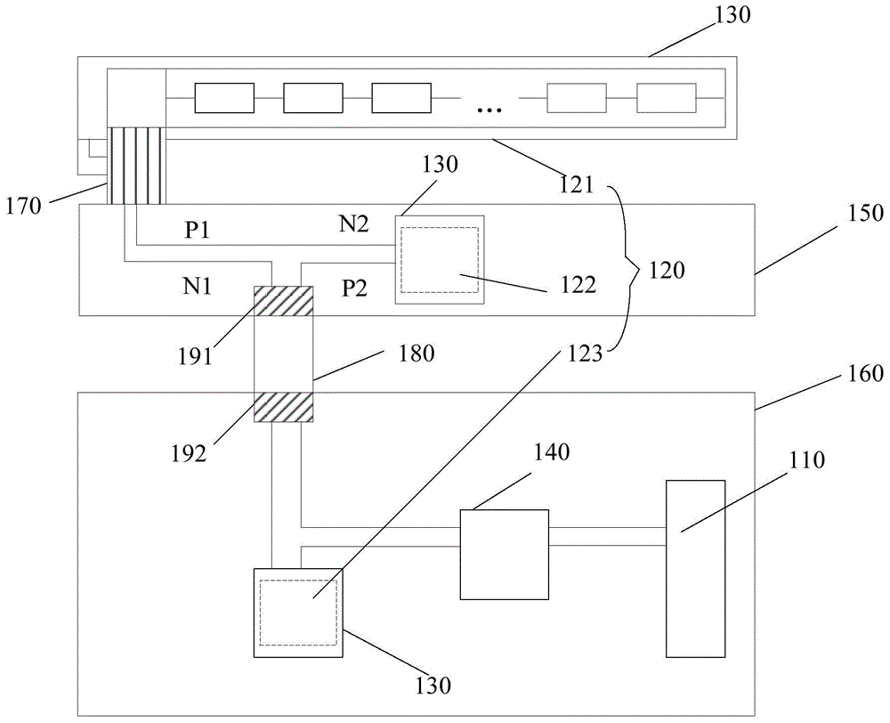
[0032] figure 1 A schematic structural diagram of an electronic device provided in Embodiment 1 of the present invention, such as figure 1 As shown, the electronic device includes: a rechargeable battery 110 , a heating element 120 , a heat conduction film, at least one thermoelectric power generation sheet 130 and a charging control circuit 140 .

[0033] The heating device 120 can be one or more. Exemplary, the heating device includes: LED, the light bar 121 on the backlight panel of the liquid crystal display and includes PowerIC (PowerIntegratedCircuit, power management integrated circuit) 122 and CPU (Central Processing Unit, central processing unit ) 123 including integrated circuit chips, etc. Wherein, the PowerIC 122 is located on the driver board 150 , and the driver board is used to drive the light bar 121 on the backlight panel of the liquid crystal display to emit light; the CPU, the charging control circuit 140 and the rechargeable battery 110 are located on the ...

Embodiment 2

[0051] Figure 4 It is a schematic structural diagram of an electronic device provided in Embodiment 2 of the present invention. This embodiment further optimizes the electronic equipment on the basis of the foregoing embodiments, and the electronic equipment includes:

[0052] The liquid crystal display 410 and the system main board 420 are respectively provided with a first interface 411 and a second interface 421 , and the two are connected through a connection line 430 . Wherein, the liquid crystal display screen also includes: a light bar 412 , an FPC414 and a PowerIC415 for connecting the light bar 412 and the PCB 413 ;

[0053] In addition to the above-mentioned devices, the electronic device also includes: a heat conduction film located on the back of the light bar 412 and the front of the PowerIC415 and CPU424, and a thermoelectric power generation sheet 440 located on the heat conduction film. The hot end of the thermoelectric power generation sheet 440 is adjacent...


PUM


Abstract

The invention discloses an electronic device. The electronic device comprises a rechargeable battery; a heating device; a heat conduction film, which is arranged on the surface of the heating device and is used for conducting the heat dissipated by the heating device; at least one temperature difference power generation piece, of which the hot end is arranged at the side, away from the heating device, of the heat conduction film, and which is used for converting the heat emitted by the heating device into electric energy; and a charging control circuit, which is electrically connected with the temperature difference power generation piece and the rechargeable battery, and is used for controlling the process of charging the rechargeable battery by utilizing the electric energy generated by the temperature difference power generation piece. According to the electronic device, the heat emitted by the component in the circuit is utilized to charge the battery, so that the problems of reducing the service life of the device and wasting energy due to the generation of a lot of heat in the working process of the electronic device are solved, and service time of the battery is increased under the condition of having no external power supply.

Description

technical field [0001] Embodiments of the present invention relate to the field of electronics, and in particular, to an electronic device. Background technique [0002] With the advancement of science and technology, electronic devices can be seen everywhere in today's human life, and there are various types. A large part of the electronic equipment is composed of light-emitting and heat-emitting devices such as displays and light-emitting devices, printed circuit boards (Printed Circuit Board, PCB) and integrated circuit chips. [0003] Among them, the light emitting diode (Light Emitting Diode, LED) in the light emitting device is widely used, and can be used as an indicator light of various switching devices, a flash light for taking pictures, and a backlight source of a liquid crystal display in an existing display, etc. [0004] In the current LED lighting technology, the luminous efficiency of LED is only 130Lm / W, and the efficiency of converting electrical energy in...

Claims


Application Information

Patent Timeline
Patent Type & Authority Applications(China)
IPC IPC(8): H02J7/32H02N11/00
CPCY02B40/00
Inventor 吴春芸林沛炀双强杨天宇
Owner KUSN INFOVISION OPTOELECTRONICS
Why Eureka
Try Eureka