
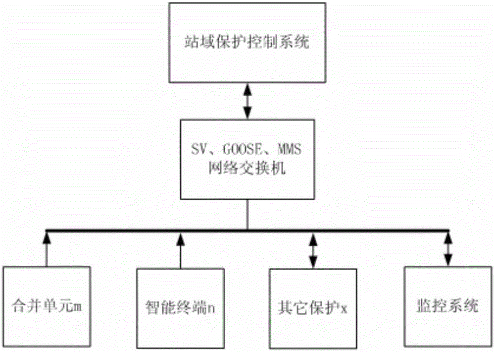
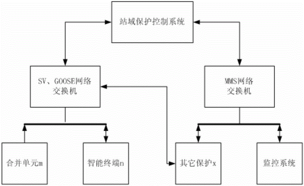
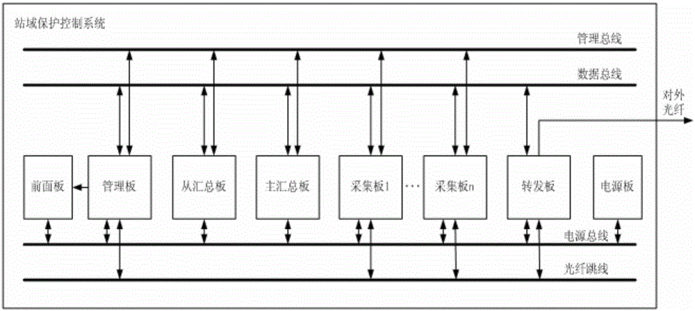
Smart substation station domain protection control system framework

A smart substation and control system technology, applied in the direction of electrical components, circuit devices, etc., can solve problems affecting system stability, difficulty in accessing the entire station AC and switch redundancy optimization, lack of system stability functions, etc., to achieve improved The effect of reliability and stability

Active Publication Date: 2015-12-30
STATE GRID CORP OF CHINA +2
View PDF5 Cites 4 Cited by
  • Summary
  • Abstract
  • Description
  • Claims
  • Application Information

AI Technical Summary

Problems solved by technology

[0004] (1) Most of the protection equipment in the station adopts a single configuration. If the protection equipment fails, the system will have a protection blind zone, which will affect the reliability of the system operation;
[0005] (2) Although the analog quantities and switching quantities of each interval, component, and switch of the smart substation have been digitized, these digital quantities have not been fully utilized to optimize the relevant protection. That is to say, the mainstream operation mode of the current smart substation is direct mining and direct jumping (That is, the merging unit, the intelligent terminal is directly connected to the protection device without a switch), while the conventional protection device is limited by the number of optical ports that can be accessed, and it is difficult to access the AC and switching volumes of the whole station to realize the redundancy of the whole station protection optimization;
[0006] (3) The security automatic control equipment in the station mostly adopts a single set of configuration. If the automatic control equipment fails, the system security function will be missing, which will affect the stability of the system operation

Method used


Image

  • Smart substation station domain protection control system framework
  • Smart substation station domain protection control system framework
  • Smart substation station domain protection control system framework

Examples


Embodiment Construction

[0030] The present invention will be described in further detail below in conjunction with the accompanying drawings and embodiments.

[0031] Such as figure 1 , 2 As shown, the architecture of the intelligent substation station domain protection control system of the present invention includes a station domain protection control system, a network switch, a monitoring system, merging units and intelligent terminals for each interval.

[0032] The station domain protection control system is connected to the network switch through the optical port, obtains the SV analog value sent by the merging unit and the GOOSE switch value sent by the intelligent terminal, and after analysis, processing and protection control logic calculation, the GOOSE switch that needs to trip The traffic is sent to the smart terminal through the network switch. The MMS communication between the station domain protection control system and the background monitoring system is also completed through the n...


PUM


Abstract

The invention provides a smart substation station domain protection control system framework which acquires all the spaced electrical quantity and switching quantity information of the whole station through network switches and realizes intra-station protection redundancy, optimization, supplementing and safety automatic control functions by adopting a network-sampling-network-tripping mode. The smart substation station domain protection control system framework comprises merging units and smart terminals which are spaced in the station, and a background monitoring system. A substation station domain protection control system is connected with at least one group of network switches via optical fiber interfaces. The acquired SV analog quantity transmitted by the merging units in the network and GOOSE switching quantity transmitted by the smart terminals are transmitted to the control system by the network switches. After parsing processing and protection control logic calculation of the control system, the GOOSE switching quantity requiring tripping is transmitted to the corresponding smart terminals. An MMS communication protocol between the background monitoring system and the control system is connected by the network switches. Different voltage levels of protection and control functions in the station can be realized.

Description

technical field [0001] The invention relates to an intelligent secondary equipment architecture, in particular to an intelligent substation domain protection control system architecture. Background technique [0002] At present, the application of smart substations in China is gradually increasing, but the configuration of protection still inherits the characteristics of traditional relay protection. The protection configuration of smart substations in the prior art does not take advantage of the technical advantages of smart substations to optimize the backup protection, and there are still traditional protection configurations. flaws inherent in the fallback protection. [0003] There are still the following deficiencies in the protection and control configuration of 110kv and below voltage level substations: [0004] (1) Most of the protection equipment in the station adopts a single configuration. If the protection equipment fails, the system will have a protection blin...

Claims


Application Information

Patent Timeline
IPC IPC(8): H02J13/00
CPCY02E60/00
Inventor 刘更原宇光徐成斌刘宏君田伟宋晓亮陈策富辜新宇
Owner STATE GRID CORP OF CHINA
Learn More