Matrix switching system and matrix switching method for switching among multi-format video signals

A video signal, matrix switching technology, applied in the security, video and audio fields, can solve the problems of signal security, real-time concerns, cumbersome wiring, short transmission distance, etc., to achieve the effect of convenient long-distance transmission and simplified use

Active Publication Date: 2015-12-30
大连科迪视频技术有限公司
View PDF5 Cites 11 Cited by
  • Summary
  • Abstract
  • Description
  • Claims
  • Application Information

AI Technical Summary

Problems solved by technology

[0002] In the audio-visual system and security system, the matrix switcher is an indispensable device; especially with the emergence of a variety of front-end signal sources, multi-format matrixes have emerged as the times require, which greatly facilitates the integration and installation of the system; but the signal acquisition end There are often many uncertainties in the distance to the equipment control room. The short distance is less than a few meters, and the distance is more than thousands of kilometers. Even if the best coaxial cable is used, the high-definition signal can only be transmitted t

Method used


Image

  • Matrix switching system and matrix switching method for switching among multi-format video signals
  • Matrix switching system and matrix switching method for switching among multi-format video signals
  • Matrix switching system and matrix switching method for switching among multi-format video signals

Examples


Example Embodiment

[0041] In order to make the objectives, technical solutions and advantages of the present invention clearer, the present invention will be further described in detail below with reference to the accompanying drawings.

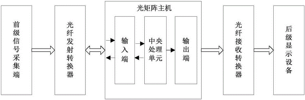
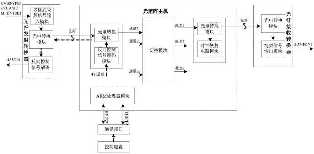
[0042] like figure 1 — Figure 10 As shown, the present invention proposes an optical matrix system for switching multi-format video signals, which meets the needs of the audio-video and security industries for long-distance real-time transmission of multi-format video signals.

[0043] The current common multi-format matrix greatly facilitates the switching and processing of video and audio signals at the signal acquisition end of different types of interfaces, but the distance between the signal acquisition end and the equipment control room is different, and common metal cables often cannot meet the signal distance. The need for distance transmission, and the security and real-time performance of optical signals just make up for this need; so the optical fi...


PUM


Abstract

The invention discloses a matrix switching system and a matrix switching method for switching among multi-format video signals. The system comprises an optical fiber emission convertor, an optical matrix main unit and an optical fiber receiving convertor, wherein the optical fiber emission convertor is used for recognizing and converting the multi-format video signals into unified optical signals, emitting the optical signals to the optical matrix main unit, and receiving reversely transmitted optical signals to form control data; the optical matrix main unit is used for fulfilling conversion and transmission of the video signals, synchronously converting the control data corresponding to the video signal into optical signals in the video signal conversion and transmission process, and reversely transmitting the optical signals to the optical fiber emission convertor; the optical fiber receiving convertor is used for converting the optical signals transmitted by the optical matrix main unit into video signals taking the format of recognizable electrical signals of backward stage display equipment. The matrix switching system and the matrix switching method have the advantages that the signals of the input-output paths are mutually independent, so that when one path of signals get out of order, the transmission of other paths of signals can be prevented from being impacted; meanwhile, the problem that the transmission of the control signals requires a special cable can be solved effectively as reverse data are synchronously transmitted in optical fibers.

Description

technical field [0001] The invention relates to the technical field of video and audio and the technical field of security, in particular to a matrix switching system and a matrix switching method for switching multi-format video signals. Background technique [0002] In video and audio systems and security systems, matrix switchers are indispensable equipment; especially with the emergence of diversified front-end signal sources, multi-format matrixes emerge as the times require, which greatly facilitates the integrated installation of the system; however, the signal acquisition end There is often a lot of uncertainty in the distance from the equipment control room. The nearest one is less than a few meters, and the far one is more than thousands of kilometers. Even if the best coaxial cable is used, the high-definition signal can only be transmitted to a few hundred meters. If the IP network known for its long-distance transmission is used, there will be concerns about sig...

Claims


Application Information

Patent Timeline
IPC IPC(8): H04N5/268H04N7/22
Inventor 马庆强周春雷
Owner 大连科迪视频技术有限公司
Why Eureka
Try Eureka