Impeller for a Kaplan turbine

An impeller and turbine technology, applied in hydropower, mechanical equipment, engine components, etc., can solve problems such as environmental pollution, and achieve the effect of reducing the possibility of cavitation

Inactive Publication Date: 2015-12-30
VOITH PATENT GMBH
View PDF6 Cites 0 Cited by
  • Summary
  • Abstract
  • Description
  • Claims
  • Application Information

AI Technical Summary

Problems solved by technology

Potential for environmental contamination when hub leaks if oil is used

Method used


Image

  • Impeller for a Kaplan turbine
  • Impeller for a Kaplan turbine
  • Impeller for a Kaplan turbine

Examples


Embodiment Construction

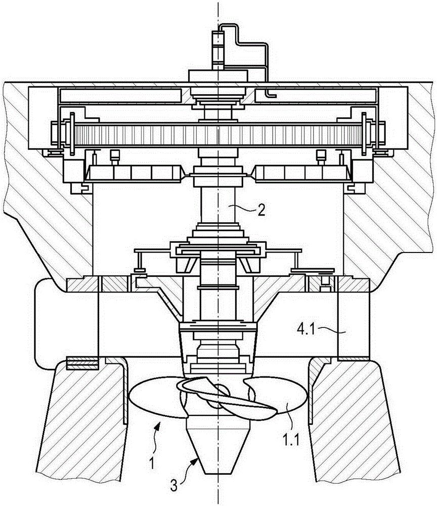
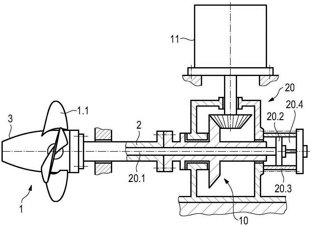
[0017] figure 1 The Kaplan turbine shown in contains an impeller 1 supported by a shaft 2 . The shaft 2 is arranged vertically. The water turbine mechanism includes adjustable blades 1.1.

[0018] The shaft contains a hub 3 at its free end. A guide vane ring 4 is further provided. A guide vane ring 4 is mounted in the hub 3 . The guide vanes 4.1 are also adjustable.

[0019] The adjustment unit according to the invention is used for adjustment, wherein an adjustment force proportional to the head is applied.

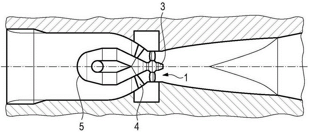
[0020] figure 2 The Kaplan turbine shown in is a tubular turbine with a horizontal axis. Hub 3 is also shown in figure 2 middle. The turbine also contains the figure 1 The same components of the turbine. The figure illustrates the impeller 1 and the further guide blade ring 4 .

[0021] A casing 5 surrounding the generator is provided. The generator is located on the shaft of the impeller 1.

[0022] In this case also set something like figure 1 The adju...


PUM


Abstract

The invention relates to an impeller for a Kaplan turbine, comprising the following features or components: a shaft, a plurality of blades; a hollow hub which is located on the free end of the shaft and which carries the blades; an adjustment device for rotating the blades around axes of rotation perpendicular to the axis of rotation of the shaft. The invention is characterized by the following features: the interior of the hub is connected to a source of compressed air; branch lines are provided inside the hub to supply the compressed air to bearings or other lubrication points for the adjustment device.

Description

technical field [0001] The invention relates to a Kaplan water turbine. (See eg DE10100963A1) Background technique [0002] This Kaplan water turbine includes, as its related parts, an impeller, a guide wheel and a casing. The impeller is provided with adjustable blades and is coupled to the shaft. [0003] Kaplan turbines have a vertical axis, but there are also Kaplan turbines with a horizontal axis. [0004] A particularly interesting application of a Kaplan turbine with a horizontal axis is already known. In this case, for example, in river hydropower plants, the gates of the dam or the retaining barrage are equipped with a large number of Kaplan turbines, eg with 6, 12, 24 or more turbines. A single Kaplan turbine is obviously very small in this case. In case of damage it can be easily and quickly removed and exchanged for a new water turbine. It is desirable to keep the construction of the water turbine as simple as possible (see eg US 5,825,094). [0005] The a...

Claims


Application Information

Patent Timeline
Patent Type & Authority Applications(China)
IPC IPC(8): F03B3/06F03B3/14
CPCF03B3/06F03B3/145F05B2260/98Y02E10/20F03B3/123F03B11/002
Inventor 格雷戈瑞·斯奈德富兰克林·斯汀森托马斯·奈德哈特
Owner VOITH PATENT GMBH
Why Eureka
Try Eureka