Automatic recovery type air dryer

An air dryer and automatic recovery technology, applied in chemical instruments and methods, separation of dispersed particles, separation methods, etc., can solve problems such as inability to air dry

Inactive Publication Date: 2016-01-06
CHONGQING UNION MACHINE MFG
View PDF1 Cites 0 Cited by
  • Summary
  • Abstract
  • Description
  • Claims
  • Application Information

AI Technical Summary

Problems solved by technology

[0005] The present invention intends to provide an automatic recovery air dryer to solve the problem in the prior art that th...

Method used


Image

  • Automatic recovery type air dryer

Examples


Embodiment 1

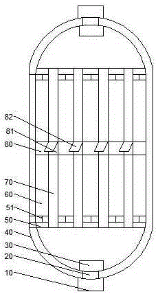
[0016] Such as figure 1 As shown, the automatic recovery air dryer has a scheme as follows: comprising a cylinder 40, the upper end of the cylinder 40 is provided with an air outlet one and a fan one connected with the air outlet one, and the lower end of the cylinder is provided with an air outlet two 20 and connected with the air outlet The blower fan 2 10 that tuyere 2 20 is connected to. The middle part of cylinder 40 is provided with air inlet 81, and cylinder 40 is provided with upper, middle and lower tube plates, and vertical drying layer 70 is arranged between upper and middle tube plates and between middle and lower tube plates, The tuyere 81 communicates with the drying layer 70 through the middle tube plate 80. The drying layer 70 contains a desiccant. The drying layer 70 is evenly arranged in the horizontal direction of the cylinder 40. A heating layer 60 is arranged between the drying layers 70. The air outlet and A humidity sensor 30 is provided inside the air ...


PUM


Abstract

The invention discloses an automatic recovery type air dryer. The scheme is as follows: the automatic recovery type air dryer comprises a barrel, wherein an air outlet I and a draught fan I connected with the air outlet I are formed in and arranged at the upper end of the barrel; an air outlet II and a draught fan II connected with the air outlet II are formed in and arranged at the lower end of the barrel; an air inlet is formed in the middle of the barrel; the barrel is internally provided with an upper pipe plate, a middle pipe plate and a lower pipe plate; vertical drying layers are arranged between the upper pipe plate and the middle pipe plate, and between the middle pipe plate and the lower pipe plate; the air inlet is communicated with the drying layers through the middle pipe plate; each drying layer contains a drying agent; the drying layers are uniformly arranged on the barrel in the horizontal direction; heating layers are arranged between the drying layers; humidity sensors are arranged in the air outlet I and the air outlet II; the humidity sensors are connected with a controller; the controller is connected with the draught fan I, the draught fan II and the heating layers. The automatic recovery type air dryer aims at solving the problems in the prior art that the drying agent is recovered after the drying of the air is stopped, and the air cannot be continuously dried.

Description

technical field [0001] The present invention relates to an automatic recovery air dryer. Background technique [0002] At present, the industrial air drying treatment usually adopts the adsorption method, that is, the moisture and part of the oil in the air are absorbed by the desiccant, so that the humid air becomes dry air. Since there is no chemical reaction between the moisture and these desiccants, the amount of the desiccant has not decreased, so it is usually not necessary to add additional desiccants. dry function. [0003] In order to solve the above problems, the patent document with the publication number CN204684922U discloses an air dryer. The two sides of the plate are respectively provided with a front deflector and a rear deflector, between the front deflector and the middle deflector is filled with a desiccant a, between the middle deflector and the rear deflector Filled with desiccant b, the center of the container is provided with a groove along the cir...

Claims


Application Information

Patent Timeline
IPC IPC(8): B01D53/26
Inventor 邓雪峰
Owner CHONGQING UNION MACHINE MFG
Why Eureka
Try Eureka