Sludge drying and feeding device and feeding method

A sludge drying and feeding device technology, applied in the direction of dehydration/drying/concentrated sludge treatment, etc., can solve the problems of easy blockage of conveying pipes, high moisture content of dehydrated cake, and uniform distribution of difficult sludge drying devices, etc., to achieve The effect of avoiding waste of resources

Active Publication Date: 2020-12-18
山东达源环保工程有限公司
View PDF7 Cites 0 Cited by
  • Summary
  • Abstract
  • Description
  • Claims
  • Application Information

AI Technical Summary

Problems solved by technology

[0007] Aiming at the problem that the moisture content of the dehydrated cake in the prior art is high, it is easy to block the conveying pipeline, and it is difficult to distribute evenly in the sludge drying device

Method used


Image

  • Sludge drying and feeding device and feeding method
  • Sludge drying and feeding device and feeding method

Examples


Embodiment 1

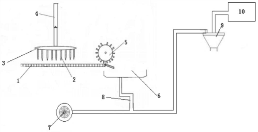
[0042] Such as figure 1 As shown, this embodiment provides a sludge drying and feeding device, including a dehydrated cake conveyor belt 1, a sludge dividing device 3 is provided on the dehydrated cake conveying belt 1, and the sludge dividing device 3 is a fork with spikes 2 Type structure, the dehydrated cake is divided into pieces, which is convenient for subsequent processing. The dehydrated cake conveyor belt 1 is a chain conveyor belt, and the chain conveyor belt is transported by a chain conveyor. There is a toggle device 5 at the end of the dehydrated cake conveyor belt 1 to prevent the dehydrated cake from being too viscous to fall into the hopper. The toggling device 5 is a turntable structure with a plurality of paddles.

[0043] At the end of the chain conveyor belt, each segment of the chain forms a gap with the gap between the chains, and the assembly position of the toggle device satisfies that the shortest distance between the entire toggle device and the con...

Embodiment 2

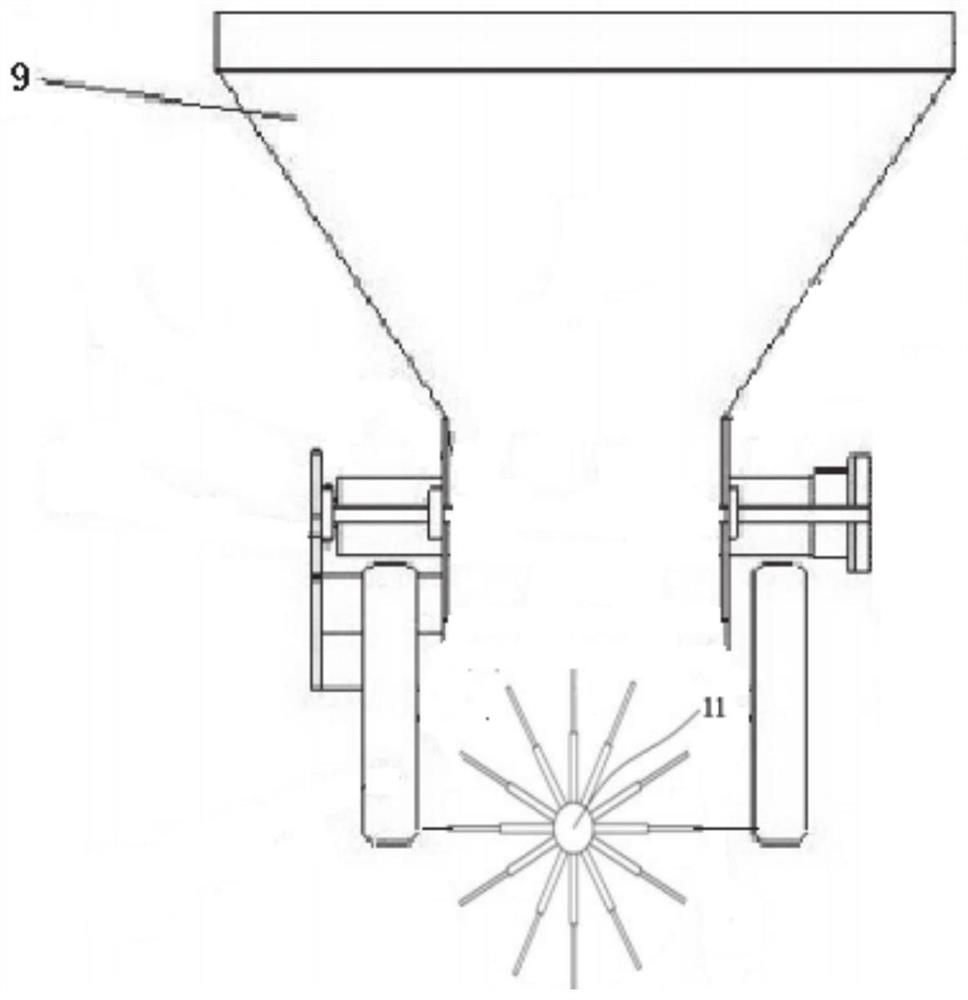
[0050] This embodiment provides a sludge drying and feeding method, which is carried out in the sludge drying and feeding device shown in Example 1. It includes the following steps: place the dehydrated cake on the dehydrated cake conveyor belt 1, the dehydrated cake moves with the dehydrated cake conveyor belt 1, falls into the lower hopper 6 at the end of the dehydrated cake conveyor belt, and enters the dilute phase conveyance along the outlet of the lower hopper 6 The pipeline 8 starts the fan 7 to divide the dehydrated cake into small pieces of sludge, and enters the gas-material separation device 9 along the dilute phase conveying pipeline 8. The sludge exits the sludge outlet of the gas-material separation device 9, and the gas is separated from the gas material. The gas outlet of the device 9 enters the suction device 10 . Start the windmill 11, and the windmill 11 rotates to provide wind power, and the sludge is thrown out along the tangential direction of the windmil...

Embodiment 3

[0056] This embodiment provides a sludge drying and feeding method, which is carried out in the sludge drying and feeding device shown in Example 1. It includes the following steps: place the dehydrated cake on the dehydrated cake conveyor belt 1, the dehydrated cake moves with the dehydrated cake conveyor belt 1, falls into the lower hopper 6 at the end of the dehydrated cake conveyor belt, and enters the dilute phase conveyance along the outlet of the lower hopper 6 The pipeline 8 starts the fan 7 to divide the dehydrated cake into small pieces of sludge, and enters the gas-material separation device 9 along the dilute phase conveying pipeline 8. The sludge exits the sludge outlet of the gas-material separation device 9, and the gas is separated from the gas material. The gas outlet of the device 9 enters the suction device 10 . Start the windmill 11, and the windmill 11 rotates to provide wind power, and the sludge is thrown out along the tangential direction of the windmil...


PUM


Abstract

The invention relates to the field of sludge treatment, and particularly provides a sludge drying and feeding device and a feeding method. The sludge drying and feeding device comprises a dewatered sludge cake conveying belt and a discharging hopper located at the tail end of the dewatered sludge cake conveying belt, an outlet of the discharging hopper is connected with a dilute phase conveying pipe at a certain angle, a fan is arranged at an inlet of the dilute phase conveying pipe, a gas-material separation device is arranged at an outlet of the dilute phase conveying pipe, and a gas outletof the gas-material separation device is connected with a gas suction device. And a windmill is arranged at a sludge outlet of the gas-material separation device. The problems that dehydrated mud cakes are high in water content, the conveying pipe is easily blocked, and the dehydrated mud cakes are difficult to uniformly distribute in a sludge drying device are solved.

Description

technical field [0001] The disclosure relates to the field of sludge treatment, and specifically provides a sludge drying and feeding device and a feeding method. Background technique [0002] The statements herein merely provide background information related to the present disclosure and may not necessarily constitute prior art. [0003] With the development of my country's social economy, the acceleration of urbanization and the improvement of people's living standards, the amount of urban domestic sewage has increased sharply. As an auxiliary product of sewage treatment in sewage treatment plants, sludge is rich in harmful substances such as organic humus, bacterial cells, parasite eggs and heavy metals. It is a potential secondary pollution source and causes great environmental pollution. With the rapid increase of sludge production, more and more attention has been paid to the disposal of sludge. [0004] Traditional sludge treatment methods include stable landfill,...

Claims


Application Information

Patent Timeline
Patent Type & Authority Applications(China)
IPC IPC(8): C02F11/13
CPCC02F11/13
Inventor 严希海戚玉玺严谨刘华霞
Owner 山东达源环保工程有限公司
Why Eureka
Try Eureka