Supercharge Your Innovation With Domain-Expert AI Agents!

Machining cutter preventing orifice edge breakage

A technology for machining cutting tools and edge chipping, which is applied in the direction of manufacturing tools, metal processing equipment, drilling tool accessories, etc. It can solve the problems of low efficiency, many processes, and edge chipping of holes, so as to reduce costs, improve product quality, reduce The effect of the process

Inactive Publication Date: 2016-01-06
NANYUE FUEL INJECTION SYST CO LTD
View PDF9 Cites 3 Cited by
  • Summary
  • Abstract
  • Description
  • Claims
  • Application Information

AI Technical Summary

Problems solved by technology

[0003] The design problem to be solved by the present invention is: in view of the existing drilling, expanding, and chamfering processing methods, there are holes in the tool hole after drilling, many processes, and low efficiency. Chipping processing tools can solve the hole chipping phenomenon, improve product quality, improve work efficiency, and reduce costs

Method used


Image

  • Machining cutter preventing orifice edge breakage
  • Machining cutter preventing orifice edge breakage

Examples


Embodiment Construction

[0012] In order to make the technical means, creative features, objectives and effects achieved by the present invention easy to understand, the present invention will be further elaborated below.

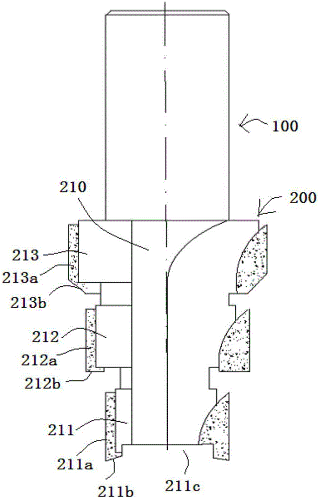
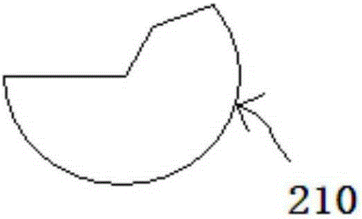
[0013] see figure 1 and figure 2 The shown processing tool for preventing hole chipping includes a cutter bar 100 and a cutter body 200 connected to the front end of the cutter bar. The cutter body 200 includes a cylinder 210 without a fan-shaped corner block, and a cylinder 210 without a fan-shaped corner block. That is, a fan-shaped corner block is dug out for the periphery of the cylinder, such as figure 2 shown. The cylinder 210 is sequentially provided with a first notch annular knife surface 211 , a second notch annular knife surface 212 and a third notch annular knife surface 213 whose outer diameter gradually increases from the front end to the rear end, and the first notch annular knife surface A first sharpening layer 211a, a second sharpening layer 212a and a third ...


PUM


Abstract

The invention discloses a machining cutter preventing orifice edge breakage. The machining cutter comprises a cutter bar and a cutter body connected to the front end of the cutter bar. The cutter body comprises a cylinder body without fan-shaped corner blocks. The cylinder body is sequentially provided with a first corner-free annular cutter face, a second corner-free annular cutter face and a third corner-free annular cutter face from the front end to the rear end, wherein the external diameters of the first corner-free annular cutter face, the second corner-free annular cutter face and the third corner-free annular cutter face are gradually increased. A first cutter sharpening layer is arranged on the peripheral surface of the first corner-free annular cutter face, a second cutter sharpening layer is arranged on the peripheral surface of the second corner-free annular cutter face, and a third cutter sharpening layer is arranged on the peripheral surface of the third corner-free annular cutter face. The first cutter sharpening layer, the second cutter sharpening layer and the third cutter sharpening layer integrate the functions of trepanning, chambering, fine boring, orifice chamfering and the like, cutter change is not needed in the operation process, the number of processes is reduced, the product quality is improved, equipment and personnel are reduced, the work efficiency is improved, and the cost is lowered.

Description

technical field [0001] The invention relates to the field of processing tools, in particular to a processing tool suitable for processing thin-walled holes with castings and preventing hole chipping. Background technique [0002] Hole machining is widely used in the machinery industry and is the basic process in machining. Existing hole processing is mainly processed by methods such as drilling, reaming, drilling, and boring. Large hole processing is solid processing or with casting reserved holes. Hole processing with casting thin-walled surfaces is also available in the machinery industry, but generally it is processed by conventional tools, such as: drilling, reaming, drilling, boring and other methods. However, if drilling is used, the product will experience edge collapse during the processing. Contents of the invention [0003] The design problem to be solved by the present invention is: in view of the existing drilling, expanding, and chamfering processing methods...

Claims


Application Information

Patent Timeline
IPC IPC(8): B23B51/08
CPCB23B51/08
Inventor 龙美彪欧阳玲湘陈美勇刘剑立
Owner NANYUE FUEL INJECTION SYST CO LTD
Features
  • R&D
  • Intellectual Property
  • Life Sciences
  • Materials
  • Tech Scout
  • Unparalleled Data Quality
  • Higher Quality Content
  • 60% Fewer Hallucinations
Learn More