Supercharge Your Innovation With Domain-Expert AI Agents!

Clamping fixture and application method thereof

A clamping and jig technology, applied in the direction of clamping, positioning devices, manufacturing tools, etc., can solve the problems of high cost, poor adaptability, unsuitable for small batch production, etc., and achieve low production cost, high processing accuracy and simple structure Effect

Inactive Publication Date: 2016-01-06
FOEHL CHINA CO LTD
View PDF11 Cites 3 Cited by
  • Summary
  • Abstract
  • Description
  • Claims
  • Application Information

AI Technical Summary

Problems solved by technology

This kind of in-line special machine can complete the processing of two threaded holes with only one clamping, and the production efficiency is high. However, because the special machine is limited to the production of a single workpiece, it has poor adaptability and high cost, and is not suitable for small batch production.

Method used


Image

  • Clamping fixture and application method thereof
  • Clamping fixture and application method thereof

Examples


Embodiment Construction

[0041] In order to make the object, technical solution and advantages of the present invention clearer, the present invention will be further described in detail below in conjunction with the embodiments. It should be understood that the specific embodiments described here are only used to explain the present invention, not to limit the present invention.

[0042] figure 1 It is a schematic diagram of a clamping fixture of the present invention. The clamping fixture includes a base plate 1, a pair of rotating shaft positioning mounting plates 2, a pair of bearings 3, a workpiece clamping limit plate 4, a first toggle clamp mounting plate 6, a first toggle clamp 7, a pair of second toggle Clamp mounting plate 8, a pair of second toggle clamps 9, and a first limiting block 10 and a second limiting block 11.

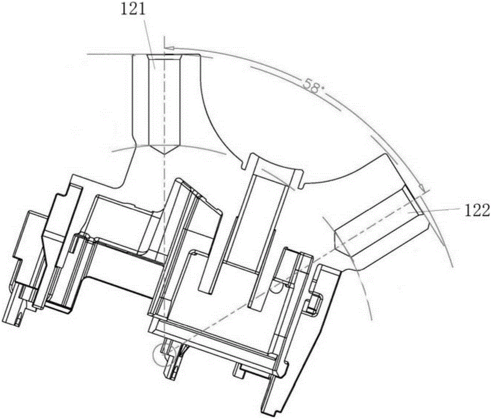
[0043] figure 2 It is a schematic diagram of an exemplary workpiece suitable for the clamping fixture of the present invention, in figure 2 The workpiece shown has a ...


PUM


Abstract

The invention discloses a clamping fixture which comprises a bottom plate, a pair of rotation shaft positioning and mounting plates, a pair of bearings, a rotation shaft, a workpiece clamping and limiting plate, a first toggle clamp mounting plate, a first toggle clamp, a pair of second toggle clamp mounting plates, a pair of second toggle clamps and at least one limiting block. The clamping fixture can effectively simplify working processes and is simple in structure and low in cost. The clamping fixture can process two holes at a certain angle on a general drilling machine and a general tapping machine only through one time of clamping. The invention further discloses a method for drilling and tapping by using the clamping fixture.

Description

technical field [0001] The invention relates to a clamping fixture, in particular to a clamping fixture for drilling / tapping and a use method thereof. Background technique [0002] Due to the complex structure of zinc alloy die-casting workpieces, some features are processed by machining after die-casting, such as drilling, tapping, reaming, and end face milling. To match it, drilling machines, tapping machines, milling machines, and fixtures matching the workpiece are required, and even some features require special equipment to complete the processing. [0003] For example, on a typical car lock bracket, there are two deep threaded holes set at a certain angle to match the bolts. Since the holes have an angle of 58 degrees, they cannot be directly die-cast, so the bottom must be processed by drilling. hole, and then tapped on the bottom hole to form the final threaded hole. Since the general-purpose drilling machine is generally only suitable for drilling in one directio...

Claims


Application Information

Patent Timeline
Patent Type & Authority Applications(China)
IPC IPC(8): B23Q3/06
CPCB23Q3/062
Inventor 陈月柏
Owner FOEHL CHINA CO LTD
Features
  • R&D
  • Intellectual Property
  • Life Sciences
  • Materials
  • Tech Scout
  • Unparalleled Data Quality
  • Higher Quality Content
  • 60% Fewer Hallucinations
Learn More