
An energy-saving device that automatically adjusts brightness, adjusts heat flow, and shields infrared radiation

A technology of infrared radiation and energy-saving devices, which is applied in the field of energy-saving devices that regulate heat flow, shield infrared radiation, and automatically adjust brightness. It can solve problems such as increased installed capacity of building refrigeration and air-conditioning equipment, increased design load of air-conditioning and heating, and fluctuations in power consumption of equipment. , to achieve the effect of increasing natural lighting, reducing heating energy consumption, and reducing heating energy consumption

Inactive Publication Date: 2017-05-17
NORTH CHINA UNIVERSITY OF TECHNOLOGY
View PDF7 Cites 0 Cited by
  • Summary
  • Abstract
  • Description
  • Claims
  • Application Information

AI Technical Summary

Problems solved by technology

In terms of indoor heat gain, due to the transparency and thermal conductivity of glass and other materials relative to the wall, this makes the building gain too much solar radiation heat during the day, and the building loses a lot of heat through the glass curtain wall at night, which not only increases The design load of air-conditioning and heating of the building is increased, which increases the installed capacity of the building's refrigeration and air-conditioning equipment and increases the investment. Moreover, due to the large fluctuation of the building load, the power consumption of the equipment fluctuates greatly, which increases the impact on the power grid.

Method used


Image

  • An energy-saving device that automatically adjusts brightness, adjusts heat flow, and shields infrared radiation
  • An energy-saving device that automatically adjusts brightness, adjusts heat flow, and shields infrared radiation
  • An energy-saving device that automatically adjusts brightness, adjusts heat flow, and shields infrared radiation

Examples


Embodiment 1

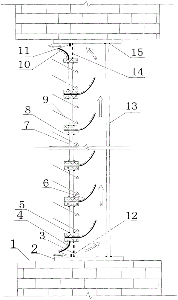
[0042] as attached figure 1 As shown, the energy-saving device for automatically adjusting brightness, adjusting heat flow, and shielding infrared radiation includes a base 2, a vent hole 3, a bimetal 4, a card slot 5, a bimetal 6, glass 7, and a support frame 8. Bimetal sheet 10, positioning bar 11, positioning bar 12, glass 13, air hole 14, card slot 15. One end of the bimetal 6 is fixed on the support frame 8, and the other end can deflect freely. A card slot 5 is fixed on the support frame 8 , and the card slot 5 fixes the glass 7 . Glass 13 is fixed on one side of bimetal 6 free ends. When the bimetal sheet 6 is straightened, it can contact the glass 13 to form a conduction heat bridge. The device includes several bimetal sheets 6 , support frames 8 and glass 7 . There are several groups of bimetal sheet 6, support frame 8, draw-in groove 5 and glass 7 along the height direction of the device. Each bimetal sheet 6 and support frame 8 constitute a unit for automatic l...

Embodiment 2

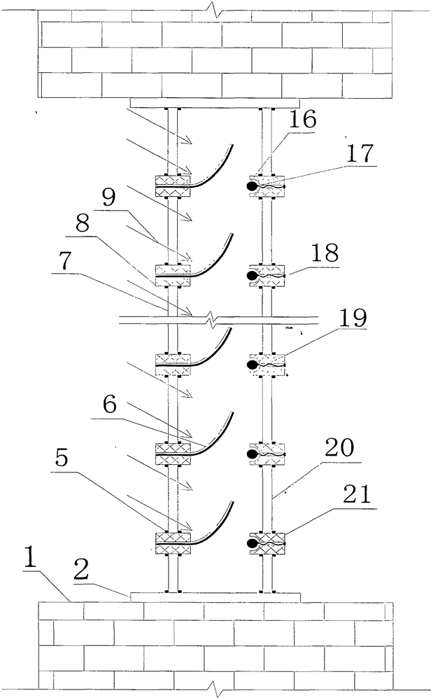
[0047] as attached figure 2 As shown, the energy-saving device for automatically adjusting brightness, adjusting heat flow, and shielding infrared radiation includes: base 2, card slot 5, bimetal 6, glass 7, support frame 8, spherical heat-conducting base 16, connecting Point 17, connection point 18, spring 19, glass 20, support frame 21. One end of the bimetal sheet 6 is fixed on the support frame 8, and the other end can be bent freely. A card slot 5 is fixed on the support frame 8 , and the card slot 5 fixes the glass 7 . A card slot 5 is fixed on the support frame 21 , and the card slot 5 fixes the glass 20 . The right end of the spring 19 is fixed on the support frame 21 through the connection point 18 , and the left end of the spring 18 is connected with the spherical heat-conducting base 16 through the connection point 17 . Bimetal 6, support frame 8, draw-in groove 5, glass 7, support frame 21, spring 19, spherical heat-conducting matrix 16, glass 20 have several g...

Embodiment 3

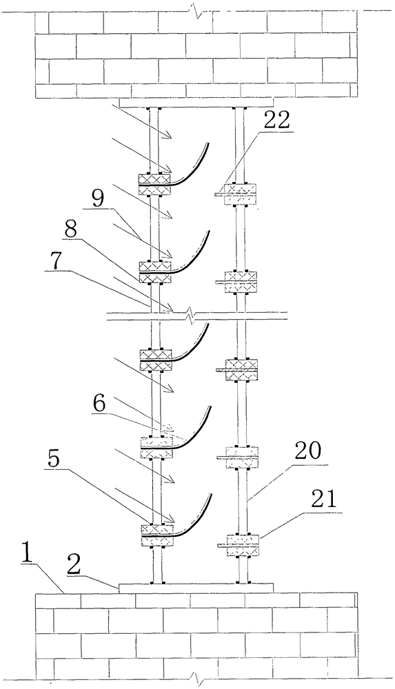
[0052] as attached image 3 As shown, the energy-saving device for automatically adjusting brightness, adjusting heat flow, and shielding infrared radiation includes: base 2, card slot 5, bimetal 6, glass 7, support frame 8, glass 20, support frame 21 . The flexible heat-conducting substrate 22 . One end of the bimetal sheet 6 is fixed on the support frame 8, and the other end can be bent freely. A card slot 5 is fixed on the support frame 8 , and the card slot 5 fixes the glass 7 . A card slot 5 is fixed on the support frame 21 , and the card slot 5 fixes the glass 20 . The flexible heat-conducting base 22 is fixed on the supporting frame 21 and has a left end protruding. There are several groups of bimetal sheet 6, support frame 8, card slot 5, glass 7, support frame 21, flexible heat-conducting matrix 22, and glass 20 along the height direction of the device.

[0053] When the free end of the bimetal 6 is above the flexible heat-conducting substrate 22 and is in a low-t...


PUM


Abstract

The invention provides an energy-saving device capable of automatically adjusting brightness and heat flow and shielding infrared radiation. The energy-saving device comprises a bimetallic strip, a support frame, glass and the like. The bimetallic strip is bent at high temperature and blocks sunlight, the sunlight entering an indoor environment is reduced, indoor brightness is reduced, indoor radiation heat gains are reduced, an airflow channel can be formed in the device or a thermal bridge between pieces of the glass is interrupted, and heat transferred from the device to the indoor environment is reduced. The bimetallic strip unbends at medium temperature, blocking of the sunlight is reduced, the sunlight entering the indoor environment is increased, the indoor brightness is improved, the thermal bridge is conducted, and heat transfer coefficients of the device are increased. The bimetallic strip is bent at low temperature and shields infrared radiation from the indoor environment to an outdoor environment, indoor heat dissipation is reduced, the thermal bridge is interrupted, and the heat transfer coefficients of the device are reduced. The device can automatically adjust the indoor brightness and indoor heat gains and shield infrared radiation according to change of solar radiation and outdoor temperature, and energy consumption of daylighting, air conditioning and heating of a building is reduced.

Description

technical field [0001] The invention relates to the fields of solar energy utilization and building energy saving, and can also be applied to fields such as agricultural engineering, and more specifically relates to an energy-saving device that automatically adjusts brightness, adjusts heat flow, and shields infrared radiation. Background technique [0002] The proportion of transparent materials such as glass curtain walls in modern buildings is increasing. The adoption of large-area glass curtain walls increases the artistic design of the building and improves the aesthetics of the building, but it also brings some problems in terms of building lighting and energy consumption. Buildings with large-area glass curtain walls have a large proportion of the external window area to the external wall area, so the building's lighting and air-conditioning heating loads will be greatly affected by the external environment. Generally speaking, in summer and at noon of a day, the sol...

Claims


Application Information

Patent Timeline
Patent Type & Authority Patents(China)
IPC IPC(8): E06B9/28E06B5/16E04B1/74E04B2/88
Inventor 李志永刘维付学友石茜茜
Owner NORTH CHINA UNIVERSITY OF TECHNOLOGY
Learn More