Servo-valve-driven high-speed composite oil cylinder

A composite oil cylinder and servo valve technology, applied in the direction of fluid pressure actuating devices, etc., can solve the problems of large nominal flow rate, large motor power, large required flow rate, etc., and achieve small effective cross-sectional area, large pressure capacity, and practical performance. Good results

Inactive Publication Date: 2016-01-06
湖北海岚数控机床有限公司
View PDF0 Cites 1 Cited by
  • Summary
  • Abstract
  • Description
  • Claims
  • Application Information

AI Technical Summary

Problems solved by technology

[0002] Ordinary hydraulic presses usually use a piston cylinder as the main drive cylinder. When driving downward, since the downward acting cylinder is a rodless chamber with a large area, the required flow is large. If a servo valve or proportional switch valve is used to control, the nominal flow of the valve is required. Very large, high cost; and the flow rate of the pump is large, the power of the motor is large, and it is not energy-saving
[0003] Forging machinery requires high speed, high efficiency, high precision, etc. Specifically, it requires the press to go down and return quickly, the pressurization speed is stable, the overall speed of the press is fast, and the beat is high; at the same time, when the slider goes down and returns quickly, no slider is required How to reduce the work done by the cylinder at this stage is beyond the reach of traditional piston cylinders

Method used


Image

  • Servo-valve-driven high-speed composite oil cylinder

Examples


Embodiment Construction

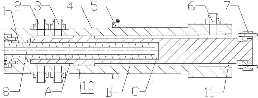
[0016] The present invention as figure 1 shown.

[0017] A high-speed composite oil cylinder driven by a servo valve, including a cylinder body 4, a piston rod 9 is assembled in the cylinder body 4, and a mounting flange 7 is arranged on the top of the piston rod 9, and the tail of the piston rod 9 is hollow, and There is an embedded composite plunger cylinder 1, and the other end of the embedded composite plunger cylinder 1 is fixedly connected with the cylinder body 4. The embedded composite plunger cylinder 1 is provided with a through fast lower chamber oil inlet 8, and the fast lower chamber The oil inlet 8 is connected with the external oil circuit;

[0018] A guide ring 10 is provided between the middle and lower part of the outer wall of the piston rod 9 and the inner wall of the cylinder body 4, and the piston rod 9 stretches out from the guide ring 2 2 at one end of the cylinder body 4, and the guide ring 10, guide ring 2 in the cylinder body 4 A return chamber B i...


PUM


Abstract

The invention provides a servo-valve-driven high-speed composite oil cylinder. The tail part of a piston rod is hollow, and an embedded composite piston cylinder is arranged in the tail part of the piston rod. The embedded composite piston cylinder is fixedly connected with the other end of a cylinder body, and a through rapid-declining chamber oil inlet is formed in the embedded composite piston cylinder and connected with an external oil way. A guide ring I is arranged between the middle-lower part of the outer wall of the piston rod and the inner wall of the cylinder body, and the piston rod extends out from a guide ring II at one end of the cylinder body. A return chamber is formed between the guide ring I and the guide ring II in the cylinder body, and the guide ring I and the other end in the cylinder body form a pressurizing chamber. The top end of the embedded composite piston cylinder and the hollow tail part of the piston rod form a rapid-declining chamber, and a return chamber oil inlet is formed in the cylinder body at the top of the return chamber and communicated with the return chamber. A rapid-declining autonomous oil absorption inlet and a pressurizing chamber oil inlet are formed in the cylinder body outside the pressurizing chamber, and the two inlets are communicated with the pressurizing chamber. The servo-valve-driven high-speed composite oil cylinder realizes rapid declining, low-speed pressurizing and rapid return and has the advantages of being easy to assemble, good in practical performance and high in efficiency.

Description

technical field [0001] The invention relates to a high-speed composite oil cylinder driven by a servo valve, which has the advantages of fast descending, fast return, large pressurizing capacity and high efficiency. Background technique [0002] Ordinary hydraulic presses usually use a piston cylinder as the main drive cylinder. When driving downward, since the downward acting cylinder is a rodless chamber with a large area, the required flow is large. If a servo valve or proportional switch valve is used to control, the nominal flow of the valve is required. It is very large, and the cost is high; and the flow rate of the pump is large, the power of the motor is large, and it is not energy-saving. [0003] Forging machinery requires high speed, high efficiency, high precision, etc. Specifically, it requires the press to go down and return quickly, the pressurization speed is stable, the overall speed of the press is fast, and the beat is high; at the same time, when the sli...

Claims


Application Information

Patent Timeline
Patent Type & Authority Applications(China)
IPC IPC(8): F15B15/14
Inventor 何毅张健袁金刚李福金苟俊杰
Owner 湖北海岚数控机床有限公司
Why Eureka
Try Eureka