

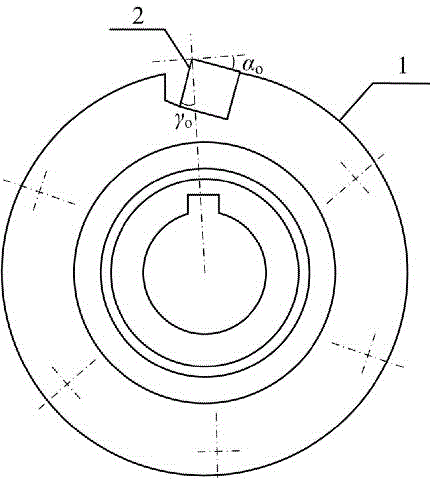
Optimum design method for anterior angle and relief angle of groove milling tool
A technology that optimizes design and tool rake angle. It is used in calculations, special data processing applications, instruments, etc. It can solve problems such as difficulty in ensuring optimization accuracy and consideration of instantaneous average temperature of tools.
- Summary
- Abstract
- Description
- Claims
- Application Information
AI Technical Summary
Problems solved by technology
Method used
Image

Examples
Embodiment Construction
[0069] The rake angle and back angle optimization design method of the groove milling tool of the present invention comprises the following steps,
[0070] (1) Firstly, according to the processing conditions, determine the combination of rake angle and back angle of various tools that can be used;
[0071] (2) Determine the physical performance parameters of cutting tools and workpieces by consulting literature or experimental tests;
[0072] (3) According to the actual cutting conditions, the combinations of cutting parameters to be analyzed are determined through the orthogonal experiment design method;
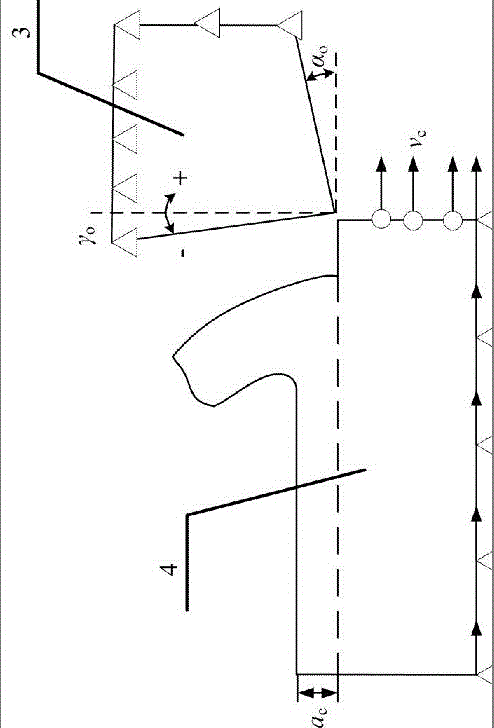
[0073] (4) Convert milling to right-angle free cutting, use commercial finite element software, set various relevant parameters, and perform two-dimensional right-angle free cutting finite element simulation;
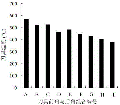
[0074] (5) According to the finite element simulation results, the heat flux on the tool and the tool-chip contact length are calculated;
[0075] (6) Through theo...
PUM
 Abstract
Description
Claims
Application Information