
A Rotor Axially Interleaved Bearingless Flux Switching Motor

A magnetic flux switching motor and bearingless technology, which is applied in the direction of synchronous machines, electrical components, electromechanical devices, etc., can solve the problems of complex current control, non-current, three-phase current asymmetry, etc., and achieve the effect of solving complex calculations

Active Publication Date: 2017-10-31
NANJING UNIV OF AERONAUTICS & ASTRONAUTICS
View PDF6 Cites 0 Cited by
  • Summary
  • Abstract
  • Description
  • Claims
  • Application Information

AI Technical Summary

Problems solved by technology

It can be seen that the sine degree of the three-phase current is relatively high, but they all contain different DC components, resulting in the asymmetry of the three-phase current
The complexity of its current solution is simpler than the method with the lowest copper consumption, but it is still much more complicated than the traditional bearingless permanent magnet synchronous motor
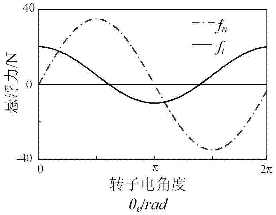
[0018] Both of the above two current control methods have the problems of relatively complicated current control and asymmetrical three-phase current, so they are not ideal control methods. The key reason is that image 3 There is a DC component in the levitation force component parallel to the coil shown in

Method used


Image

  • A Rotor Axially Interleaved Bearingless Flux Switching Motor
  • A Rotor Axially Interleaved Bearingless Flux Switching Motor
  • A Rotor Axially Interleaved Bearingless Flux Switching Motor

Examples


Embodiment Construction

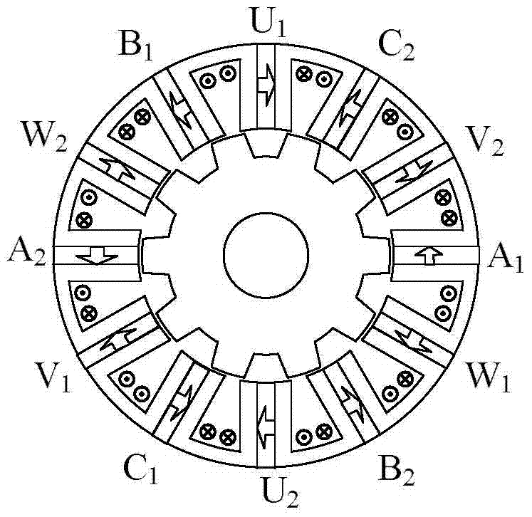
[0040] The invention discloses a rotor axial interlaced bearingless magnetic flux switching motor, which comprises a first stator, a second stator, a first rotor and a second rotor;

[0041] The first stator and the second stator have the same structure, are connected in the middle by superimposing non-magnetic material layers, and the teeth of the two stators are in the same position and their axes coincide;

[0042] The stator teeth of the first stator and the second stator are embedded with permanent magnets, which are magnetized along the circumferential direction, and the magnetization directions of the adjacent permanent magnets in the circumferential direction are opposite;

[0043] The magnetization directions of the permanent magnets in the two stator teeth at the same position of the first stator and the second stator are opposite;

[0044] The first stator and the second stator are provided with the same winding coil on the two stator teeth at the same position;

...


PUM


Abstract

The invention discloses a rotor axial staggered bearing-free flux switching motor, so as to optimize and improve the problem of complex suspension force control of a general bearing-free flux switching motor. A motor rotor is divided into two sections in the axial direction. Two rotors are staggered at the electrical angle of 180 degrees, and then are connected in parallel to form a whole body. A motor stator is divided into two layers in the axial direction. Two layers are the same except that magnetization directions of permanent magnets are opposite. According to the invention, the complementary characteristic of a suspension winding of the flux switching motor is used; suspension force tangential component direct current bias produced by the energized single-phase suspension winding is eliminated; the difficulty of control is greatly simplified; and sinusoidal suspension winding current is realized in the case of constant suspension force.

Description

technical field [0001] The invention relates to the field of bearingless motors, in particular to a rotor axially staggered bearingless flux switching motor. Background technique [0002] Since there is no contact between the mechanical bearings of the bearingless motor, the stator and the rotor are completely separated, and there is no problem of mechanical wear. It has special advantages in the semiconductor industry, life sciences and other fields. The permanent magnets of traditional bearingless permanent magnet synchronous motors are usually installed on the rotor, which leads to problems such as poor heat dissipation of the rotor and the risk of thermal demagnetization of the permanent magnets. In addition, for permanent magnet surface-mounted rotors, additional protection measures are usually required to protect the permanent magnets from being damaged by centrifugal force under high-speed rotational motion, which increases the difficulty and cost of processing. In a...

Claims


Application Information

Patent Timeline
Patent Type & Authority Patents(China)
IPC IPC(8): H02K16/00H02K21/00
Inventor 倪拓成王晓琳丁强武谷雨
Owner NANJING UNIV OF AERONAUTICS & ASTRONAUTICS
Learn More