
Power supply device used for elevator brake coil

A brake coil and power supply device technology, applied in the field of elevators, can solve problems such as complex control, complex process, and large IGBT switching loss

Inactive Publication Date: 2016-01-06
IFE ELEVATORS
View PDF8 Cites 5 Cited by
  • Summary
  • Abstract
  • Description
  • Claims
  • Application Information

AI Technical Summary

Problems solved by technology

Due to the large difference between the IGBT control loop and the main circuit voltage, it is difficult to isolate the high and low voltage of the IGBT; secondly, the IGBT and PWM square wave control chips are more expensive, resulting in increased development costs; finally, the process of controlling the IGBT by the PWM wave is complicated, and Due to the high frequency of the PWM square wave, the loss of the IGBT switch is large
In summary, the disadvantages of DC step-down are: greater difficulty, higher cost, complex control, etc., and these difficulties increase the instability of the brake power supply

Method used


Image

  • Power supply device used for elevator brake coil
  • Power supply device used for elevator brake coil
  • Power supply device used for elevator brake coil

Examples


Embodiment Construction

[0025] Embodiments of the present invention will now be described with reference to the drawings, in which like reference numerals represent like elements.

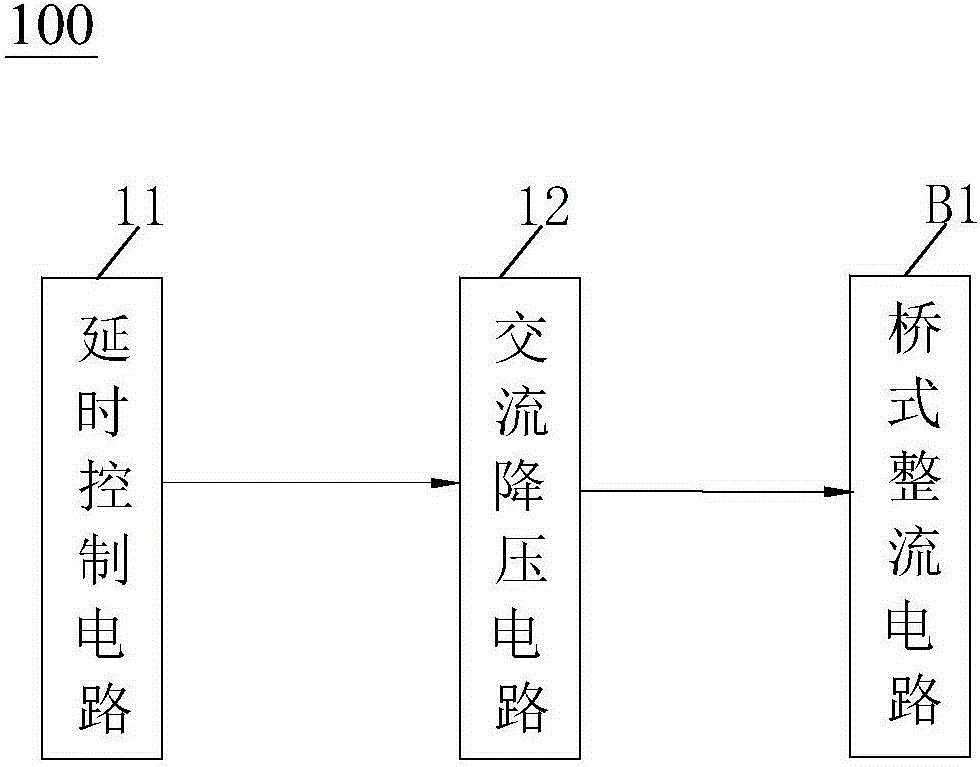
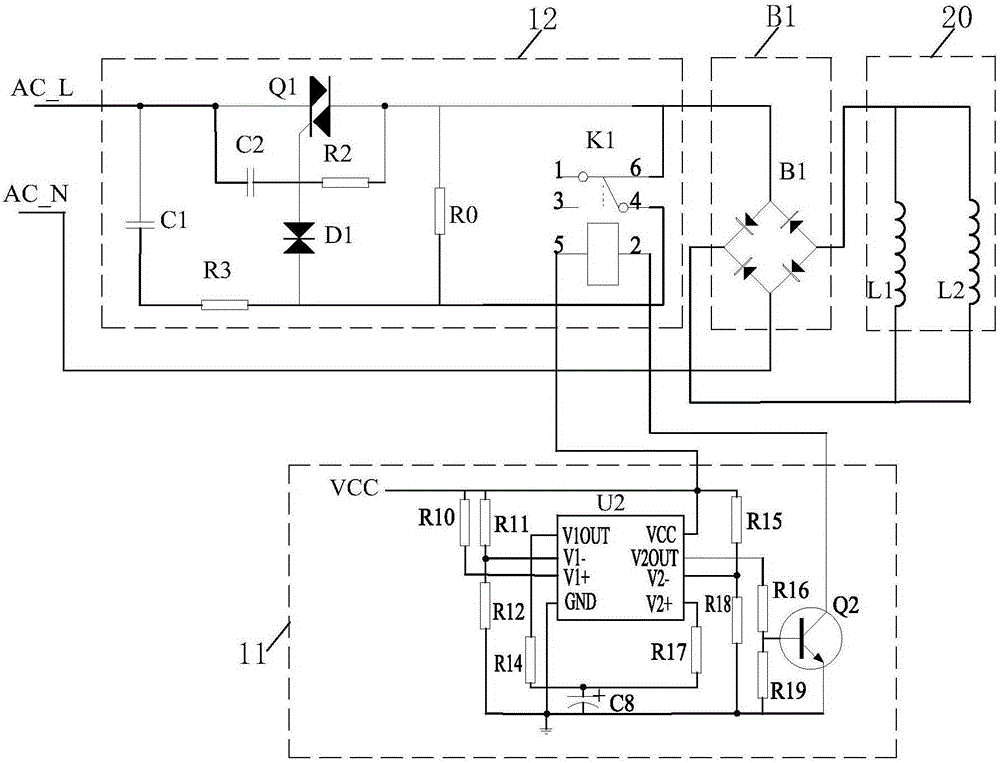
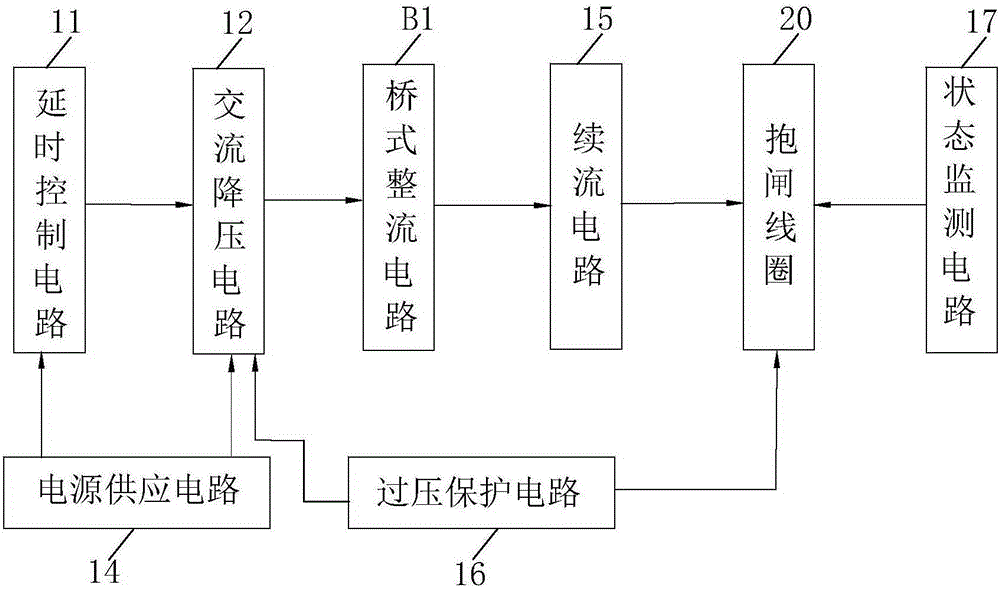
[0026] Please refer to figure 1 , the power supply device 100 used for elevator brake coils in the present invention includes a delay control circuit 11, an AC step-down circuit 12 and a bridge rectifier circuit B1, wherein the delay control circuit 11 is used to respectively Output the first control signal and the second control signal to the AC step-down circuit 12, the output terminal of the AC step-down circuit 12 is connected to the positive input terminal of the bridge rectifier circuit B1, and the negative input terminal of the bridge rectifier circuit B1 is connected to the mains The neutral line AC_N is connected, and the output end of the bridge rectifier circuit B1 is connected to the brake coil 20 . Specifically, such as figure 2 As shown, the brake coil 20 is represented by an inductance L1 and an inductan...


PUM


Abstract

A power supply device used for an elevator brake coil disclosed by the present invention comprises a time delay control circuit, an AC buck circuit and a bridge rectifier circuit B1, the time delay control circuit outputs a first control signal and a second control signal respectively when an elevator is started and the time delay time is ended, and the AC buck circuit comprises a relay K1, a capacitor C1, a resistor R0, a resistor R3, a bidirectional diode D1 and a bidirectional silicon controlled rectifier Q1. A live wire of the commercial power is connected with the first terminal of the bidirectional silicon controlled rectifier Q1, and the control end of the bidirectional silicon controlled rectifier Q1 is in series connection with the bidirectional diode D1 and then is connected with a normally-closed contact 4 of the relay K1. The capacitor C1 and the resistor R3 are connected in series and then are in parallel connection between the first terminal of the bidirectional silicon controlled rectifier Q1 and the normally-closed contact 4, and the second terminal of the bidirectional silicon controlled rectifier Q1 is connected with a common contact 6 of the relay K1. The resistor R0 is in parallel connection between the second terminal of the bidirectional silicon controlled rectifier Q1 and the normally-closed contact 4, and the normally-closed contact 4 of the relay K1 is closed and disconnected respectively according to the first and second control signals. Compared with the prior art, the power supply device used for the elevator brake coil of the present invention is simple and reliable in realization mode and low in cost, and realizes the high and low voltage isolation.

Description

technical field [0001] The invention relates to the technical field of elevators, in particular to a power supply device for elevator brake coils. Background technique [0002] The elevator brake device is an important safety component of the elevator. The reliability of the brake device opening and closing is a necessary condition for the normal operation of the elevator, and the opening and closing of the brake device are directly controlled by the current on and off in the brake coil. Determined, the brake coil has the characteristics of blocking AC and DC. Since the elevator has strict real-time requirements for the opening and closing of the brake device, in order to reduce the delay of opening and closing, the elevator brake coil often uses DC power supply, and the brake coil initiates the brake opening and maintains the opening state The required voltages are often different, and the voltage required for the brake coil to maintain the open state is lower than the vol...

Claims


Application Information

Patent Timeline
IPC IPC(8): H02M7/40
Inventor 胡文贵杨清云陈盛俊王兴东
Owner IFE ELEVATORS
Learn More