Method and corresponding device for coupling a shaft of an electric motor with a wheel shaft of an electrically powered or hybrid motor vehicle

A technology for hybrid vehicles and electric motors, applied in hybrid vehicles, engine-driven traction, electric vehicles, etc., can solve problems such as vibration, speed increase, and electric motor speed increase

Active Publication Date: 2016-01-06
RENAULT SA
View PDF4 Cites 1 Cited by
  • Summary
  • Abstract
  • Description
  • Claims
  • Application Information

AI Technical Summary

Problems solved by technology

Additional solutions exist that make it possible to rapidly increase the speed of the electric motor, which, once equal values ​​are obtained, may continue to rise, which leads to shocks

Method used


Image

  • Method and corresponding device for coupling a shaft of an electric motor with a wheel shaft of an electrically powered or hybrid motor vehicle
  • Method and corresponding device for coupling a shaft of an electric motor with a wheel shaft of an electrically powered or hybrid motor vehicle
  • Method and corresponding device for coupling a shaft of an electric motor with a wheel shaft of an electrically powered or hybrid motor vehicle

Examples


Embodiment Construction

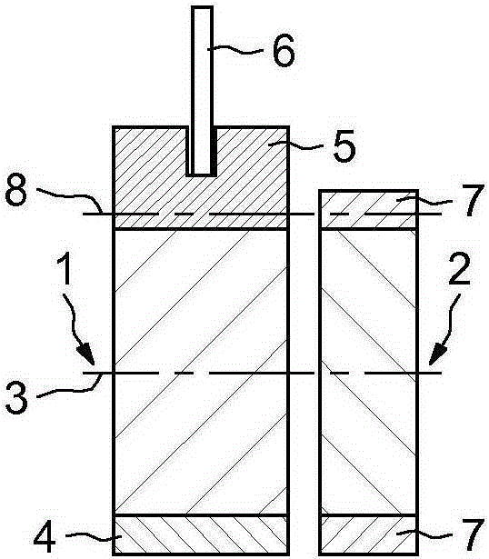
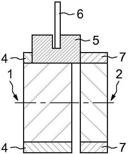
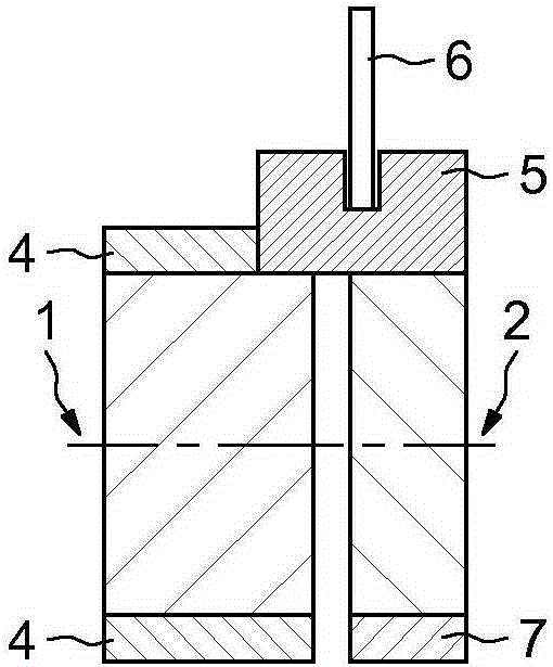
[0041] Figure 1a A first pinion 1 , for example connected to the shaft of an electric motor, and a second pinion 2 , for example connected to the shaft of a wheel, are shown. The first pinion 1 and the second pinion 2 are shown from the front, thus the axis of rotation 3 is shown with dashed lines. The pinion 1 comprises a set of teeth, one of which 4 is visible. A sliding gear 5 enabling shaft coupling is connected to the teeth of the pinion 1 . The sliding gear 5 can be moved in translation by the action of the fork 6 .

[0042] The second pinion is equipped with a plurality of teeth 7, and in Figure 1a In the case shown, these teeth can have a rotational movement only linked to the rotational movement of the wheel.

[0043] Figure 2ashows another view of pinions 1 and 2, which is the same as Figure 1a Corresponds to the sectional plan view with reference number 8 in . The sliding gear 5 comprises teeth 5 coupled with the teeth 4 of the pinion 1 . In this figure, th...


PUM


Abstract

Method and corresponding device for coupling a shaft of an electric motor with a wheel shaft of an electrically powered or hybrid motor vehicle, the method comprising: - closed-loop control to formulate a first operating setpoint (Teint) for the electric motor based on the measured rotational speed of the electric motor and on the measured rotational speed of the wheels, said control involving an integration, - formulating a second operating setpoint (Teanti) based on the measured rotational speed of the wheels to which at least one coefficient is applied, - control of the operation of the motor about a final operating setpoint (Teref) formulated by adding the first and second operating setpoints together.

Description

technical field [0001] The present invention relates to electric or hybrid vehicles, and more particularly to the coupling of the shaft of an electric motor to the shaft of a wheel. Background technique [0002] It is known that hybrid vehicles comprise two drive systems, namely a heat engine and an electric motor. Usually, when switching from one drive type to another, the coupling between these shafts is established between the shafts rotating at the same speed. For example, in a vehicle traveling at a certain speed, if the shafts of the electric motors of the vehicle are not rotating at the same speed as the wheels, the coupling between the shafts of the electric motors and the shafts of the wheels will cause vibrations. Coupling or decoupling may be performed when a speed threshold is reached. [0003] Therefore, during the coupling phase (for example, when the speed drops below a threshold again), it is necessary to control the speed of the electric motor so that its ...

Claims


Application Information

Patent Timeline
Patent Type & Authority Applications(China)
IPC IPC(8): B60W10/02B60W10/08B60W20/00F16H61/04B60L50/16
CPCB60W10/02B60W10/08F16H61/0403B60W2510/0283B60W2520/26B60W2710/083B60Y2400/421B60Y2300/73F16H2061/0474F16H2061/0078B60W50/06B60W2050/0011B60W20/40Y02T10/72F16H2061/0422
Inventor A·科特菲-谢里夫G·洛奈A·马卢姆
Owner RENAULT SA
Why Eureka
Try Eureka