

Method for manufacturing spectacle lens and coating device for coating liquid for base material of spectacle lens
A technology for spectacle lenses and a manufacturing method, which is applied in the directions of glasses/protective glasses, glasses/goggles, and devices for coating liquid on surfaces, etc., can solve the problems of difficulty in forming sufficient uniformity and the like
- Summary
- Abstract
- Description
- Claims
- Application Information
AI Technical Summary
Problems solved by technology
Method used
Image

Examples
no. 1 Embodiment approach
[0028] Below, use Figure 1 ~ Figure 3 The first embodiment of the manufacturing method of the spectacle lens and the coating liquid coating device for the spectacle lens base material of the present invention will be described in detail.
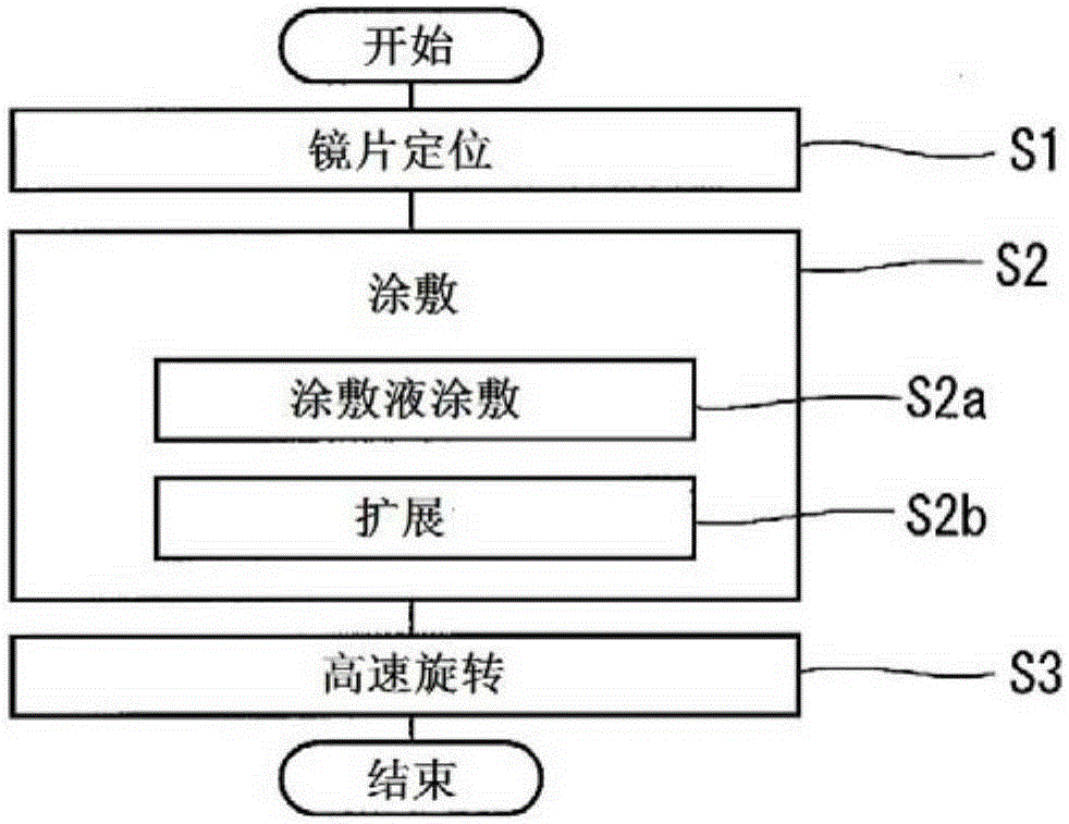
[0029] The manufacturing method of the spectacle lens of this embodiment is as follows figure 1 implemented as shown in the flowchart. That is, the lens positioning step S1, the coating step S2, and the high-speed rotation step S3 are sequentially performed. In the coating step S2, the coating liquid coating step S2a and the coating liquid spreading step S2b are sequentially performed, and the details will be described later.
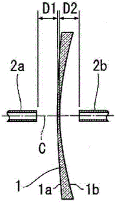
[0030] In the lens positioning step S1, such as Figure 2A As shown, the spectacle lens base material 1 is positioned between a pair of nozzles 2a, 2b for coating liquid application. The spectacle lens base material 1 is formed in a disk shape, and is arranged such that the optical axis C of the lens surfaces 1a,...
no. 2 Embodiment approach
[0062] Next, use Figure 4 The second embodiment of the manufacturing method of the spectacle lens of the present invention will be described in detail with reference to FIG. 5 . exist Figure 4 and Figure 5, for utilizing with Figure 1 ~ Figure 3 Members that are the same as or equivalent to those described will be given the same reference numerals, and detailed descriptions will be appropriately omitted.
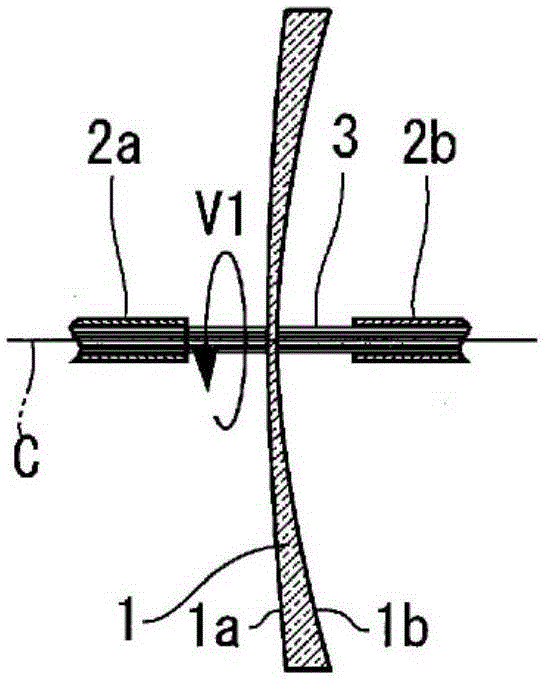
[0063] The manufacturing method of the spectacle lens of this embodiment can use image 3 The illustrated spectacle lens substrate is applied with a coating liquid coating device 11 . Also in this embodiment, the disc-shaped spectacle lens base material 1 is processed in a state where the optical axis C is directed in the horizontal direction. In addition, in this embodiment, a thermoplastic coating liquid, a thermosetting coating liquid, an ultraviolet-curable coating liquid, etc. can also be used.
[0064] In the manufacturing method of the spectacle lens of this e...
PUM
 Abstract
Description
Claims
Application Information