Unlock instant, AI-driven research and patent intelligence for your innovation.
Rolling speed optimization method with benefit control as target in cold continuous rolling process
What is Al technical title?
Al technical title is built by PatSnap Al team. It summarizes the technical point description of the patent document.
A technology of rolling speed and optimization method, which is applied in the field of metallurgical cold rolling, and can solve the problems of low benefit
Active Publication Date: 2016-01-13
唐山市榕泽钢材加工有限公司
View PDF5 Cites 9 Cited by
Summary
Abstract
Description
Claims
Application Information
AI Technical Summary
This helps you quickly interpret patents by identifying the three key elements:
Problems solved by technology
Method used
Benefits of technology
Problems solved by technology
[0003] Aiming at the problem that the increased benefit due to the reduction of power consumption per ton of steel is lower than the reduced benefit due to the reduction of production capacity due to the artificial reduction of production capacity in order to reduce the power consumption per ton of steel in the tandem cold rolling mill, the invention provides a cold rolling millRolling speed optimization method aiming at benefit control in continuous rolling process
Method used
Image
Click on the blue label to locate the original text in one second.
Reading with bidirectional positioning of images and text.
Examples
Embodiment 1
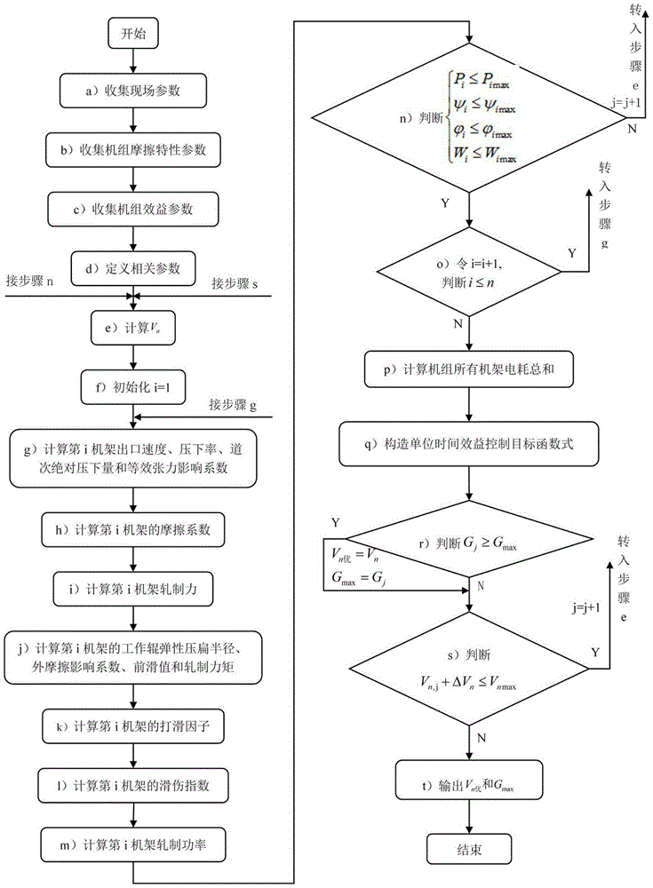
[0043] case figure 1 The overall calculation block diagram of the rolling speed optimization method with the goal of benefit control in the cold tandem rolling process is shown. First, in step (a), field parameters are collected, including: the thickness h of the entrance and exit of the five racks i-1 ,hi (mm) {(2.50, 1.85), (1.85, 1.16), (1.16, 0.82), (0.82, 0.56), (0.56, 0.45)}, five rack roll radius R i (mm) {265, 237, 249, 266, 264}, five rack motor efficiency η i {0.85, 0.84, 0.86, 0.85, 0.87}, strip density ρ=7850(kg / m 3 ), five racks emulsion flow rate Q i (L / min) {3050, 3450, 3500, 3600, 3900}, five rack strip width B i =1020(mm), Young's modulus E=210GPa, Poisson's ratio v=0.3, the average deformation resistance of five racks K mi (Mpa) {373, 475, 541, 576, 612}, tension T at the inlet and outlet of five racks i-1 , T i (Mpa) {(49, 160), (160, 170), (170, 170), (170, 180), (180, 69)}, the rolling tonnage Z of five stands after changing rolls i (t) {2228, 1940,...
Embodiment 2
[0072] First, in step (a), field parameters are collected, including: five rack inlet and outlet thicknesses h i-1 , h i (mm) {(1.82, 1.15), (1.15, 0.81), (0.81, 0.55), (0.55, 0.40), (0.40, 0.25)}, five rack roll radius R i (mm) {265, 250, 250, 250, 250}, motor efficiency η of five racks i {0.90, 0.89, 0.89, 0.85, 0.88}, strip density ρ=7850(kg / m 3 ), five racks emulsion flow rate Q i (L / min) {3000, 3400, 3600, 3800, 4200}, five rack strip width B i = 1800 (mm), Young's modulus E = 210GPa, Poisson's ratio v = 0.3, five racks average deformation resistance K mi (Mpa) {392, 485, 561, 596, 652}, tension T at the inlet and outlet of five racks i-1 , T i (Mpa) {(51, 176), (176, 176), (176, 150), (150, 176), (176, 68)}, the rolling tonnage Z of five stands after changing rolls i (t) {2028, 1830, 1750, 2120, 2450}, rolling kilometers L after the work roll change of five racks i (Km) {160, 150, 150, 160, 170}, the maximum rolling pressure P of five stands imax (t) {1500, 1500...
PUM
Property
Measurement
Unit
Young's modulus
aaaaa
aaaaa
Abstract
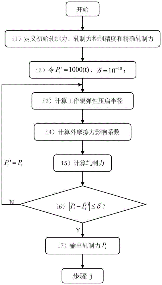
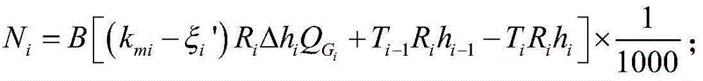
A rolling speed optimization method with benefit control as a target in the cold continuous rolling process mainly comprises the following steps that 1, field parameters are collected; 2, unit friction characteristic parameters are collected; 3, unit benefit parameters are collected; 4, relevant parameters are defined; 5, the outlet speed, the reduction rate, the gate absolute draught and the equivalent tension influence coefficient of an ith rack are calculated; 6, the friction coefficient of the ith rack is calculated; 7, the rolling force of the ith rack is calculated; 8, the working roll elastic flattening radius, the outer friction forceinfluence coefficient, the forward slip valve and the rolling torque of the ith rack are calculated; 9, the slip factor of the ith rack is calculated; 10, the slip index of the ith rack is calculated; 11, the rolling power of the ith rack is calculated; 12, the total electricity consumption of all racks of a unit is calculated; 13, a unit time benefit control target function expression is constructed; and 14, the optimal rolling speed is output. The reasonable target value for rolling speed control is set, enterprise cost is effectively reduced, and production efficiency is improved.
Description
technical field [0001] The invention belongs to the field of metallurgical cold rolling, and in particular relates to a rolling speed optimization method in the continuous cold rolling process. Background technique [0002] In recent years, due to the huge demand of household appliances, automobiles, electronics, aerospace and other industries, the cold-rolled strip production industry at home and abroad has achieved rapid development. In the past, in the production process of cold-rolled strips, the focus of on-site attention was mainly on the control of quality indicators such as shape, thickness, and surface defects. However, with the increasingly fierce competition in the steel industry and the decline in the overall profit margin of the steel industry, cost control in the production process of cold-rolled strips has been placed in an equally important position as quality control. Because for iron and steel enterprises, no matter how high the product quality is under th...
Claims
Application Information
Patent Timeline
Application Date:The date an application was filed.
Publication Date:The date a patent or application was officially published.
First Publication Date:The earliest publication date of a patent with the same application number.
Issue Date:Publication date of the patent grant document.
PCT Entry Date:The Entry date of PCT National Phase.
Estimated Expiry Date:The statutory expiry date of a patent right according to the Patent Law, and it is the longest term of protection that the patent right can achieve without the termination of the patent right due to other reasons(Term extension factor has been taken into account ).
Invalid Date:Actual expiry date is based on effective date or publication date of legal transaction data of invalid patent.
