Cutting device for angle steel

A technology of cutting device and angle steel, which is applied in the direction of shearing device, device for cutting with nibbling action, and accessory device of shearing machine, etc. It can solve the problems of operator's physical injury, large cutting volume of angle steel, and damage to the blade, etc., and guarantees Stability and consistency, ensure positioning reliability, and ensure the effect of cutting quality

Inactive Publication Date: 2016-01-13
扬州市邗江科达涂装有限公司
View PDF0 Cites 2 Cited by
  • Summary
  • Abstract
  • Description
  • Claims
  • Application Information

AI Technical Summary

Problems solved by technology

[0002] Angle steel has been widely used in various fields, but the angle steel needs to be cut into specific sizes according to different occasions. At present, the angle steel cutting machine is mainly used to cut the angle steel; but the existing angle steel cutting volume is large, the structure is complex and the cost is high.
Moreover, during the cutting process of the existing angle steel cutting machine, the angle steel will vibrate or even warp due to the shear force generated during shearing, which will not only damage the blade; and may cause injury to the operator's body
[0003] At the same time, during the cutting process, the vibration of the tool will cause some vibration of the tool in the transverse direction, so there will be a certain error in the length, so further improvement is needed

Method used


Image

  • Cutting device for angle steel
  • Cutting device for angle steel
  • Cutting device for angle steel

Examples


Embodiment Construction

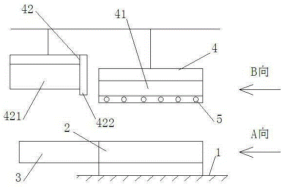
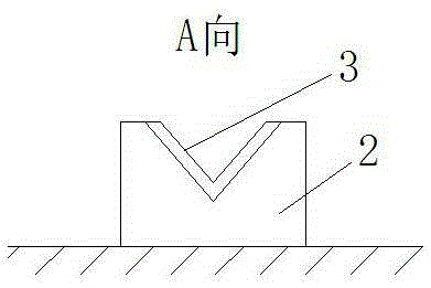
[0024] The present invention includes a frame 1 and a V-shaped positioning block 2 arranged on the frame 1, and the angle steel 3 is placed in the V-shaped positioning block 2;

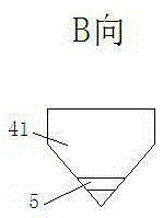
[0025] The frame 1 is provided with a cutter 4 corresponding to the V-shaped positioning block 2 on the top of the V-shaped positioning block 2, and the cutter 4 includes a positioning block 41 and a cutting knife 42;

[0026] The section of the positioning block 41 is V-shaped, corresponding to the inner wall of the angle steel 3 to form the positioning of the angle steel 3;

[0027] The section of the cutting knife 42 is V-shaped, the cutting knife 42 includes a knife body 421 and a blade 422, and the blade 422 is arranged on one side of the knife body 421 and protrudes from the knife body 421;

[0028] The positioning block 41 is arranged lower than the cutting knife 42 .

[0029] The part where the positioning block 2 contacts with the angle steel 3 is provided with an elastic layer.

[0030] Th...


PUM


Abstract

The invention relates to a cutting device for angle steel. The cutting device comprises a rack (1) and a V-shaped positioning block (2) arranged on the rack (1). The angle steel (3) is placed in the V-shaped positioning block (2). A cutter (4) which is located at the upper portion of the V-shaped positioning block (2) and corresponds to the V-shaped positioning block (2) is arranged on the rack (1). The cutter (4) comprises a positioning block (41) and a cutting knife (42). The section of the positioning block (41) is in a V shape, and corresponds to the inner wall of the angle steel (3) to position the angle steel (3). The section of the cutting knife (42) is in a V shape. The cutting knife (42) comprises a knife body (421) and a blade (422). The blade (422) is arranged on one side of the knife body (421) and protrudes out of the knife body (421). The positioning block (41) is lower than the cutting knife (42). The cutting device for the angle steel is simple in structure, and can well cut the angle steel.

Description

technical field [0001] The invention relates to an angle steel cutting device, which is applied in the technical field of angle steel cutting and processing. Background technique [0002] Angle steel has been widely used in various fields, but the angle steel needs to be cut into specific sizes according to different occasions. At present, angle steel cutting machines are mainly used to cut angle steel; but the existing angle steel cutting volume is large, the structure is complex and the cost is high. Moreover, in the cutting process of the existing angle steel cutting machine, the angle steel will vibrate or even warp due to the shear force generated during shearing, which will not only damage the blade; and may cause injury to the operator's health. [0003] Simultaneously, in the cutting process, the vibration of the cutter will cause the cutter to vibrate in the transverse direction, so there will be a certain error in the length, so further improvement is needed. Con...

Claims


Application Information

Patent Timeline
Patent Type & Authority Applications(China)
IPC IPC(8): B23D27/00B23D33/02
Inventor 李保科李平旸张古月
Owner 扬州市邗江科达涂装有限公司
Why Eureka
Try Eureka