Positioning grid for road lighting detection and road lighting detection method

A technology for positioning grids and detection methods, applied in measuring devices, instruments, etc., can solve problems such as major safety hazards, time-consuming and labor-intensive, etc., and achieve the effects of fast deployment, reduced safety hazards, and convenient transportation and use.

Inactive Publication Date: 2016-01-13
GUIZHOU TRANSPORTATION PLANNING SURVEY & DESIGN ACADEME
View PDF6 Cites 2 Cited by
  • Summary
  • Abstract
  • Description
  • Claims
  • Application Information

AI Technical Summary

Problems solved by technology

[0003] The present invention aims to solve the problems of time-consuming and labor-intensive traditional point distribution methods and relatively large safety hazards, and provides an improved positioning grid and road lighting detection method

Method used


Image

  • Positioning grid for road lighting detection and road lighting detection method
  • Positioning grid for road lighting detection and road lighting detection method

Examples


Embodiment 1

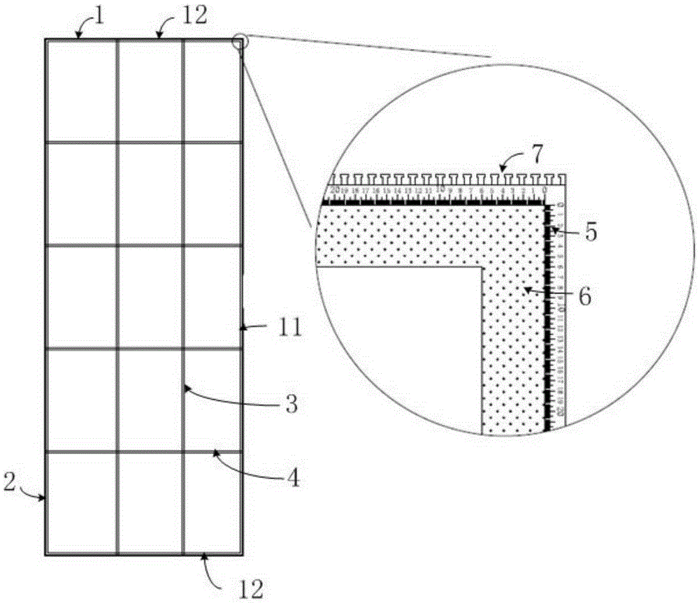
[0028] see figure 1 , is a schematic diagram of a positioning grid structure for road lighting detection according to an embodiment of the present invention.

[0029] Such as figure 1 As shown, the positioning grid used for road lighting detection includes a fixed frame 1 , a movable vertical edge 2 , at least one vertical line 3 , at least one horizontal line 4 and a scale bar 5 arranged on the fixed frame 1 and the movable vertical edge 2 .

[0030] The fixed frame 1 includes a fixed longitudinal side 11 and two equal-length transverse sides 12 located on the same side of the fixed longitudinal side 11 and perpendicular to the fixed longitudinal side 11, and the two transverse sides 12 are respectively connected to the two ends of the fixed longitudinal side 11; The two ends of the movable longitudinal side 2 are detachably connected to the two transverse sides 12 respectively; Two ends of the horizontal line 4 are detachably connected to the fixed longitudinal side 11 and...

Embodiment 2

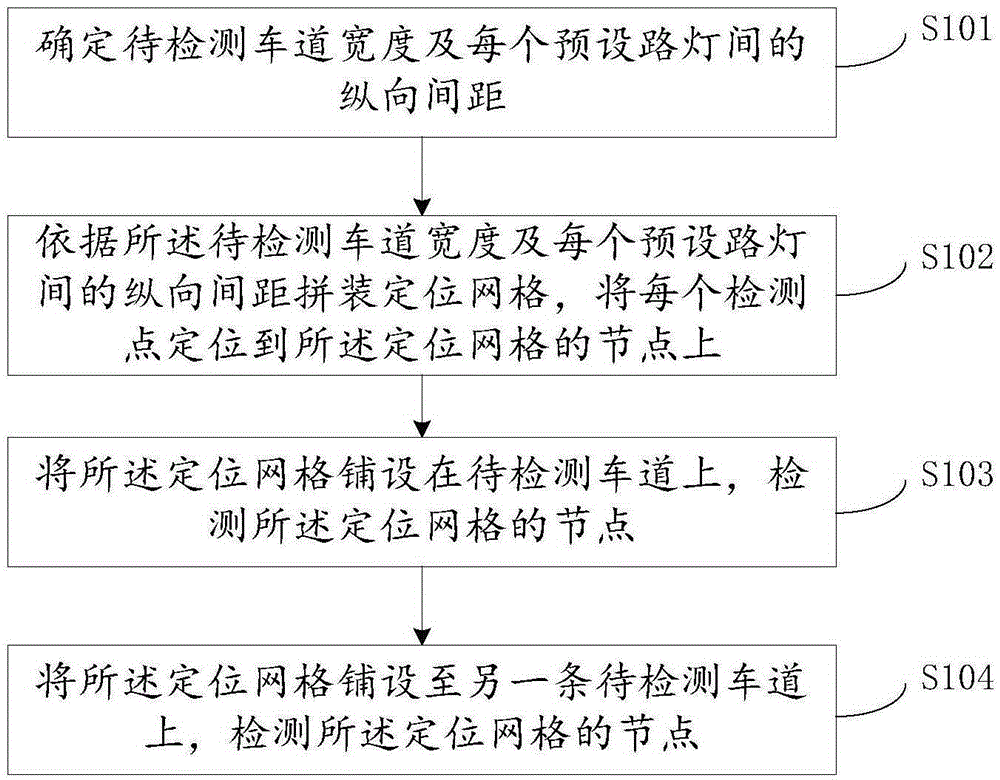
[0042] see figure 2 , is a schematic diagram of the steps of the road lighting detection method according to an embodiment of the present invention.

[0043] Such as figure 2 As shown, the road lighting detection method is based on the positioning grid provided by the present invention, and includes the following steps:

[0044] S101: Determine the width of the lane to be detected and the longitudinal distance between each preset street lamp;

[0045] The horizontal and vertical spacing of each preset street lamp is mainly calculated based on the width of the lane to be detected and the design spacing of the street lamps on site.

[0046] S102: Assemble a positioning grid according to the width of the lane to be detected and the longitudinal distance between each preset street lamp, and position each detection point on a node of the positioning grid;

[0047] Using the positioning grid provided by the present invention, the horizontal lines, vertical lines and frames are ...


PUM


Abstract

The invention relates to the field of road detection, and particularly relates to a positioning grid for road lighting detection and a road lighting detection method. The positioning grid comprises a fixed border, a movable longitudinal side, at least one longitudinal line, at least one transverse line and scales arranged on the fixed border and the movable longitudinal side. The positioning grid can be reused, is high in point distribution speed and accurate in positioning, can reduce the detection cost, is convenient to transport and use, does not cause any influence on the internal and appearance quality of a road, can be used for quickly opening the traffic to reduce potential safety hazards, and can be used for a central point distribution method and a four-corner point distribution method.

Description

【Technical field】 [0001] The invention relates to the field of road detection, in particular to a positioning grid for road lighting detection and a road lighting detection method. 【Background technique】 [0002] In the process of on-site road lighting inspection, "point layout" is a very important but most time-consuming and labor-intensive link. The traditional method is to measure the position of each measuring point with a distance measuring device in advance, and then mark it with a cone, chalk or paint. Each lane needs to be repeatedly positioned and marked, which will consume a lot of time and energy of the construction workers. In addition, the detection activities are carried out on roads that are open to traffic at night. Even if the traffic control work is done well, the detection time is too long It will also pose a greater security risk. 【Content of invention】 [0003] The invention aims to solve the problems of time-consuming and labor-intensive and relativ...

Claims


Application Information

Patent Timeline
Patent Type & Authority Applications(China)
IPC IPC(8): G01D21/00
Inventor 后明山杨黔周飞吕晓舜乔东华佘文张永逸邹子扬
Owner GUIZHOU TRANSPORTATION PLANNING SURVEY & DESIGN ACADEME
Why Eureka
Try Eureka