Load detection device

A detection device and load technology, applied in the direction of measurement device, force measurement, tension measurement, etc., can solve the problems of reduced output signal sensitivity, amplitude limitation of compressive strain, and difficulty in detecting strain, etc.

Inactive Publication Date: 2019-04-16
TOYODA IRON WORKS CO LTD
View PDF4 Cites 0 Cited by
  • Summary
  • Abstract
  • Description
  • Claims
  • Application Information

AI Technical Summary

Problems solved by technology

However, the hollow cylindrical strain body 1 is hardly deformed by a compressive force in the direction of the axis C, so there is a limit to the magnitude of the detected compressive strain
Thus, the paired axial strain sensing element 3 and the paired circumferential strain sensing element 2 may hardly detect the strain
As a result, the sensitivity of the output signal output from the output electrode 6 is reduced

Method used


Image

  • Load detection device
  • Load detection device
  • Load detection device

Examples


Embodiment Construction

[0029] Hereinafter, a load detection device according to an embodiment of the present invention will be described with reference to the drawings.

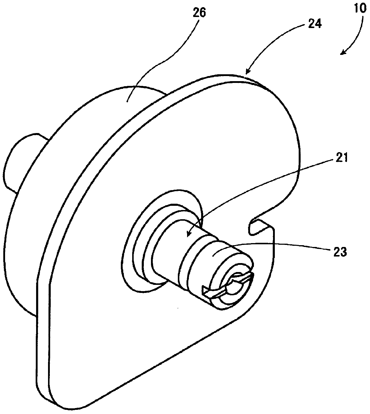
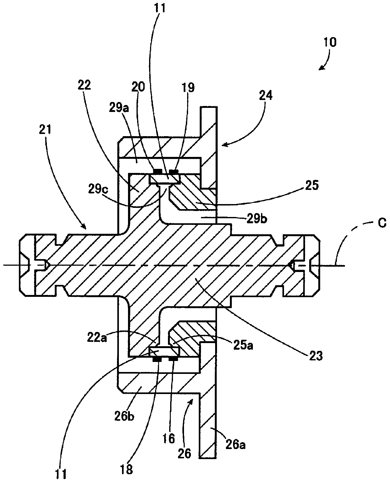
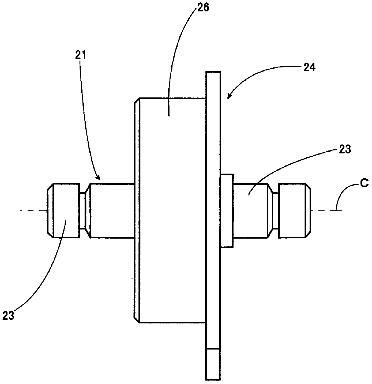
[0030] figure 1 is a perspective view showing a load detection device 10 as an example of the present invention, figure 2 yes figure 1 A longitudinal sectional view of the load detection device 10 shown, image 3 yes figure 1 A side view of the load detection device 10 is shown, Figure 4 It is a developed view of the strain body used in the load detection device 10 .

[0031] like Figure 1 to Figure 4 As shown, the load detecting device 10 includes a straining body 11 having a hollow shape, a fixing member (first part) 21 having a generally shaft-shaped configuration, and a generally ring-shaped—that is, an annular structure arranged coaxially with each other. Shape - the moving part (second part) 24. exist figure 2 and 4 , for example, a metallic hollow cylindrical strain body 11 made of ferritic stainless steel an...


PUM


Abstract

The invention relates to a load detection device, which comprises: a hollow cylindrical strain body (11), the strain body is provided with at least one strain detection element (16, etc.) on its outer peripheral surface or inner peripheral surface; a first part (21) to one axial end of the straining body; and a second part (24) secured to the other axial end of the straining body. The load detecting device is configured such that when one of the second member and the first member receives a load in a direction perpendicular to an axis (C) of the strain body, a shear force is applied to the strain body.

Description

[0001] This application is a divisional application of the invention patent application with the application number 200710139805.4 and the invention name "load detection device" submitted on August 1, 2007. technical field [0002] The present invention relates to a load detection device for detection of various loads such as a depression load of a vehicle pedal or the like, a cable tension of a vehicle parking brake, and a seat load of a vehicle seat. Background technique [0003] The traditional load detection device used for the above detection has such as Figure 9 to Figure 11 structure shown. Figure 9 is a perspective view of a conventional load detection device, Figure 10 is the expanded view of the strain body in the load detection device, Figure 11 is the circuit diagram of the load detection device. exist Figure 9 to Figure 11 Among them, the load detection device includes a hollow cylindrical strain body 1, a pair of circumferential strain detection elements...

Claims


Application Information

Patent Timeline
Patent Type & Authority Patents(China)
IPC IPC(8): G01L1/22G01L5/22G01L5/10G01G3/14
CPCG01G3/1408G01G19/4142G01L1/2225G01L5/225
Inventor 藤原升松浦昭
Owner TOYODA IRON WORKS CO LTD
Why Eureka
Try Eureka