
Signal energy synchronous transmission relay transmission method in physical layer safety communication

A technology of physical layer security and transmission method, which is applied in the field of signal energy simultaneous transmission relay transmission, and can solve the problems of low utilization rate of energy resources, difficulty in implementation, and large power consumption

Active Publication Date: 2016-01-13
XIDIAN UNIV
View PDF5 Cites 26 Cited by
  • Summary
  • Abstract
  • Description
  • Claims
  • Application Information

AI Technical Summary

Problems solved by technology

The disadvantages of this technical solution are: firstly, this method uses iterative reorganization to select two modes of relay amplification and forwarding and noise forwarding, and its computational complexity is relatively high; secondly, this method uses multiple In succession mode, its power consumption is large and the utilization rate of energy resources is low, which is not conducive to the realization of
The shortcomings of this method are: firstly, the relay node of this method needs channel estimation in each transmission period, and the transmission of signaling information brings additional energy overhead to the relay system; secondly, this method adopts the variable optimal Power split ratio ρ * and 1-ρ * , so that the power amplifier of the relay node works in a larger linear power amplification range, the circuit design complexity is high, and it is not easy to implement

Method used


Image

  • Signal energy synchronous transmission relay transmission method in physical layer safety communication
  • Signal energy synchronous transmission relay transmission method in physical layer safety communication
  • Signal energy synchronous transmission relay transmission method in physical layer safety communication

Examples


Embodiment Construction

[0048] The present invention will be further described below in conjunction with the accompanying drawings. It should be noted that this embodiment is based on the technical solution, and provides detailed implementation and specific operation process, but the protection scope of the present invention is not limited to the present invention. Example.

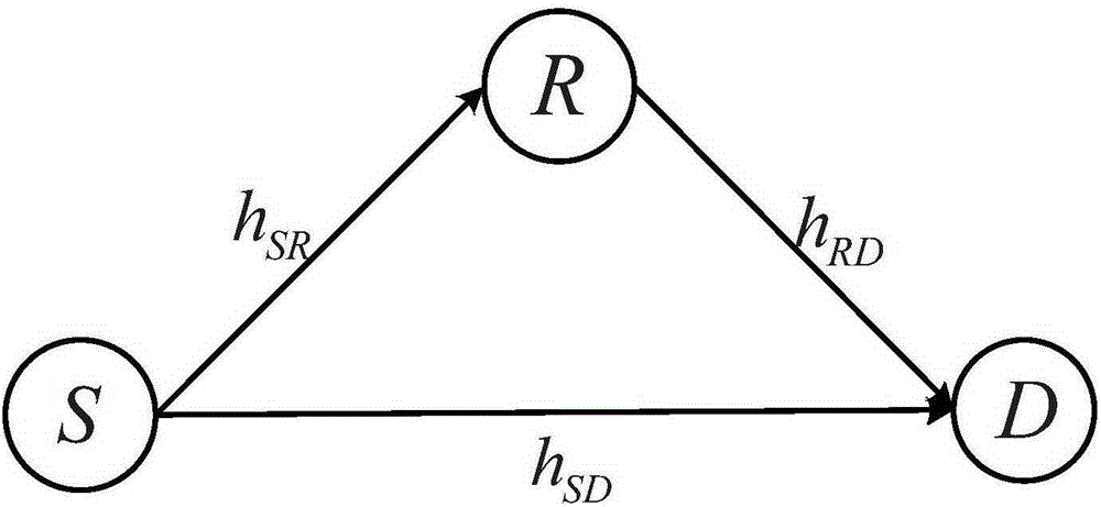
[0049] Such as figure 1 As shown, the information energy simultaneous transmission relay network used in the present invention is composed of a source node S, an unreliable relay node R and a destination node D, and all communication nodes use half-duplex mode for information transmission.

[0050] Such as Figure 4 Shown, the signal receiving circuit that the present invention uses is made up of energy receiver and information receiver, wherein, Represents the narrowband Gaussian noise of the receiving antenna, y r (t) indicates that the antenna receives the signal, Represents the processing noise of the RF signal to base...


PUM


Abstract

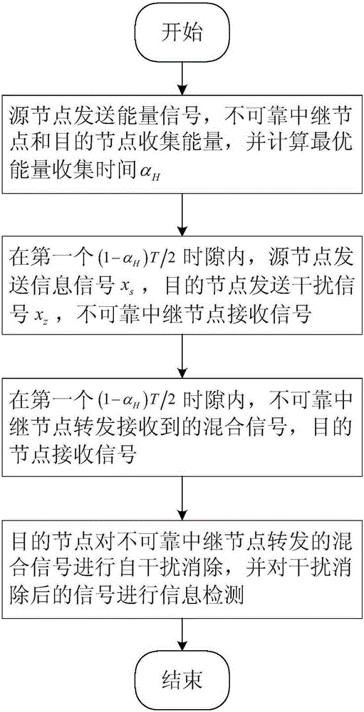
The invention discloses a signal energy synchronous transmission relay transmission method in physical layer safety communication. The method comprises the following implementation steps that: 1) a source node transmits an energy signal and calculates an optimal energy collection time scale alpha<H>, and an unreliable relay node and a destination node collect energy; 2) in a first (1-alpha<H>)T / 2 time slot, the source node transmits an information signal x<s>, the destination node transits an interference signal x<z>, and the unreliable relay node receives the signals; 3) in a second (1-alpha<H>)T / 2 time slot, the unreliable relay node forwards the received mixed signals, and the destination node receives the signals; 4) the destination node performs adaptive interference cancellation for the mixed signals forwarded by the unreliable relay node, and performs information detection on the signals of which interference is cancelled. The method provided by the invention can effectively prolong network service life of a relay network, and has low implementation complexity and high transmission safety, thus, the method can be used for a physical layer safety relay collaborative communication system.

Description

technical field [0001] The invention relates to the field of wireless communication, in particular to a relay transmission method for signal energy simultaneous interpretation in physical layer security communication. Background technique [0002] Due to the broadcast nature of wireless transmission, information transmission faces the risk of being eavesdropped by unauthorized eavesdropping nodes. Traditional encryption technology guarantees the security of information transmission through the generation and interaction of high-level keys in the network. However, this is usually based on the premise that the computing power of the nodes is limited, and the system complexity and signaling overhead are relatively large. According to information theory, physical layer security communication makes full use of the physical layer characteristics of wireless channels, so that the eavesdropping nodes can not obtain effective information, and the legitimate nodes can successfully re...

Claims


Application Information

Patent Timeline
IPC IPC(8): H04B7/155H04W52/02H04W72/04H04W72/12
CPCH04B7/15585H04W52/02H04W72/0446H04W72/12Y02D30/70
Inventor 阔永红吕璐杨龙陈健贺冰涛
Owner XIDIAN UNIV
Learn More