
Motion control method of robot in oscillatory arc welding of marine T-shaped sections

A technology of motion control and robotics, applied in arc welding equipment, manufacturing tools, welding equipment, etc., can solve the problems of closed core technology, high price, and closed interface

Inactive Publication Date: 2016-01-20
716TH RES INST OF CHINA SHIPBUILDING INDAL CORP +1
View PDF9 Cites 14 Cited by
  • Summary
  • Abstract
  • Description
  • Claims
  • Application Information

AI Technical Summary

Problems solved by technology

At present, the welding work in Dalian Shipyard is still mainly manual. Among them, the butt welding of T profiles is still mainly manual welding. This welding method has low welding efficiency and is prone to work-related accidents.
[0004] The field of automatic welding of ships is a hot spot in the field of robot application, but more than 70% of the equipment manufacturers active in the field of automatic welding are the equipment of the "four major families". The core technology is closed, the interface is not open, and the price is expensive.
However, the existing domestic robot welding technology is difficult to be promoted and applied in shipyards
Foreign manufacturers are committed to general-purpose automatic welding equipment, such as Yaskawa welding robots. The products have matured and are being promoted worldwide. However, due to the particularity of marine welding profiles, they have not been widely used in my country's marine welding equipment. promotion and application

Method used


Image

  • Motion control method of robot in oscillatory arc welding of marine T-shaped sections
  • Motion control method of robot in oscillatory arc welding of marine T-shaped sections
  • Motion control method of robot in oscillatory arc welding of marine T-shaped sections

Examples


Embodiment Construction

[0060] Exemplary embodiments of the present invention will be described in detail below with reference to the accompanying drawings. The description of the exemplary embodiments is for the purpose of illustration only, and in no way limits the invention and its application or usage.

[0061] At present, my country's ship welding is basically a manual welding method dominated by workers, with low welding efficiency and safety; in addition, due to the particularity of ship welding profiles, it is difficult for existing robot welding technology to be promoted and applied in ship welding .

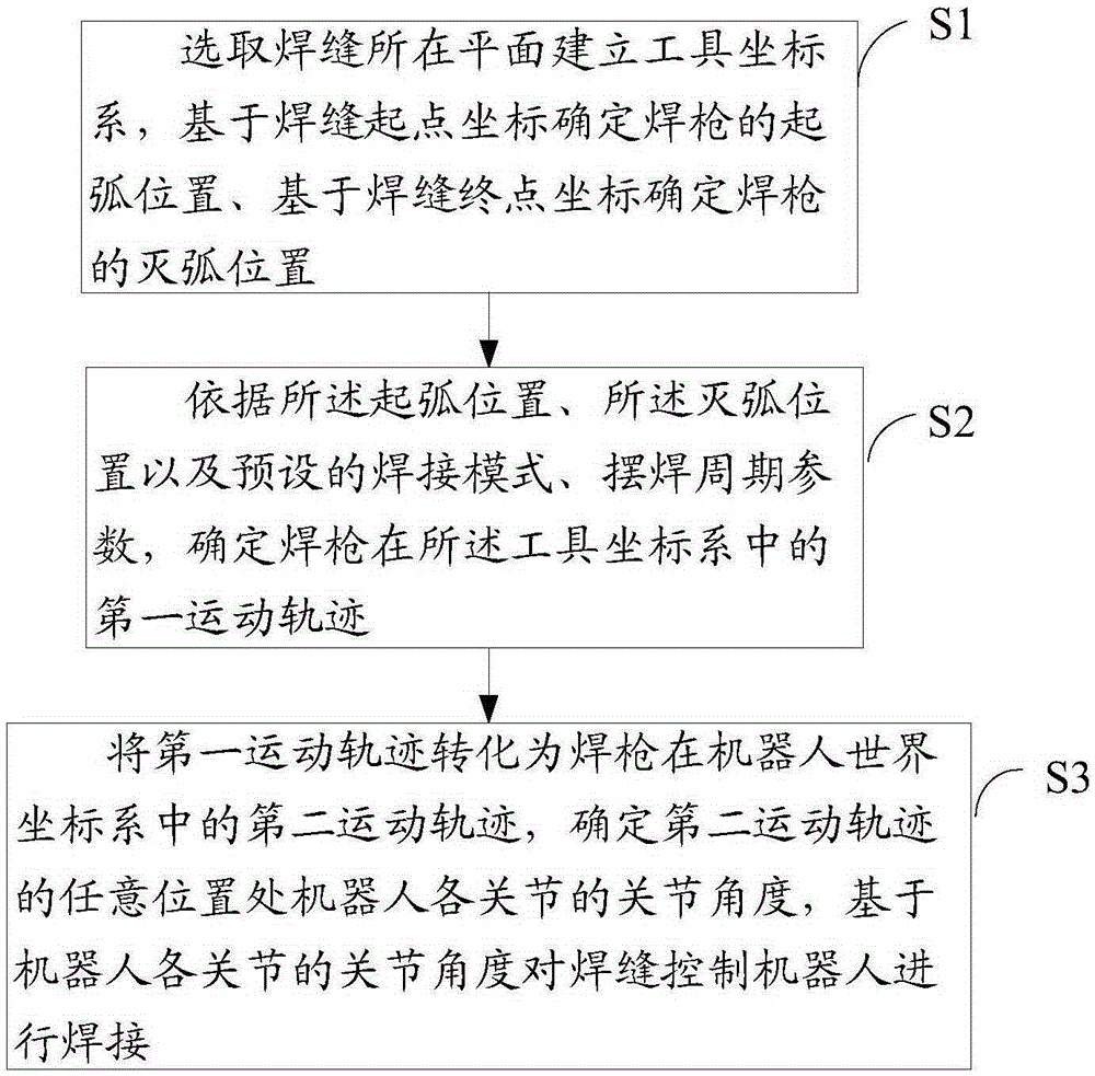
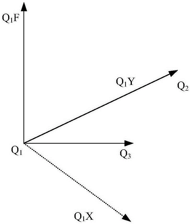
[0062] In order to solve the problems in the prior art, the present invention provides a motion control method for robotic swing arc welding of ship T-sections, by selecting the plane where the weld seam is located to establish a tool coordinate system to determine the first position of the welding torch in the tool coordinate system The motion trajectory is to convert the first motion traject...


PUM


Abstract

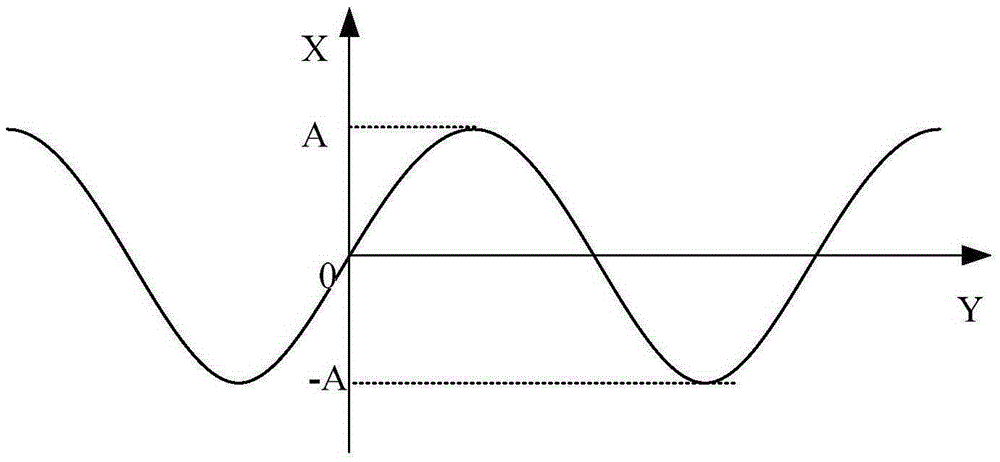
The invention discloses a motion control method of a robot in oscillatory arc welding of marine T-shaped sections. The motion control method comprises the steps of establishing a tool coordinate system on the plane where a weld joint is located, determining the arc striking position of a welding gun on the basis of the starting point coordinates of the weld joint and determining the arc extinguishing position of the welding gun on the basis of the end point coordinates of the weld joint; determining a first motion trail of the welding gun in the tool coordinate system according to the arc striking position, the arc extinguishing position, the preset welding mode and the preset oscillatory welding period parameters; converting the first motion trail into a second motion trail of the welding gun in a robot world coordinate system, determining the joint angles of joints of the robot on any position of the second motion trail, and controlling the robot to weld the weld joint on the basis of the joint angles of the joints of the robot. According to the motion control method, the motion trail of the robot and the welding gun can be accurately controlled in oscillatory arc welding, downward welding and vertical position welding of the marine T-shaped sections can be automatically achieved, the welding efficiency is high, the safety is high, and the application range is wide.

Description

technical field [0001] The invention relates to the technical field of arc welding of marine T-shaped bars, in particular to a motion control method for a robot to swing arc-welded marine T-shaped bars. Background technique [0002] The technical background related to the present invention will be described below, but these descriptions do not necessarily constitute the prior art of the present invention. [0003] According to relevant information, the welding workload accounts for 30% to 40% of the total hull construction work, the welding cost accounts for 30% to 50% of the total hull construction cost, and the man-hours required for welding account for 40% of the total hull construction man-hours. In some industrially developed countries, such as Japan, the average level of automation of ship welding has reached 70% to 80%. At present, my country's ship welding is basically a manual welding method dominated by workers, and the degree of automation is only 20% to 30%. Ta...

Claims


Application Information

Patent Timeline
IPC IPC(8): B23K9/022B23K9/095
CPCB23K9/022B23K9/0953
Inventor 李帅韩愈陈卫彬李景银花磊孙宏伟
Owner 716TH RES INST OF CHINA SHIPBUILDING INDAL CORP
Learn More