
Low-cycle fatigue cracking equipment with multi-spindle driven by the end cam of the split connecting rod

A technology of end face cam and low cycle fatigue, which is applied in the field of connecting rod cracking processing, can solve the problems of affecting the loading speed of the cracking cylinder, low cracking efficiency, limited application, etc., and achieve the goal of reducing energy consumption, wide application range and broad application prospects Effect

Active Publication Date: 2017-06-20
XI AN JIAOTONG UNIV
View PDF7 Cites 0 Cited by
  • Summary
  • Abstract
  • Description
  • Claims
  • Application Information

AI Technical Summary

Problems solved by technology

[0003] The existing cracking equipment can only process a single connecting rod, and the cracking efficiency is low; due to the use of hydraulic quasi-static loading, the pressure requirements for the main cylinder are relatively high, and the hydraulic circuit pipe diameter, valve diameter, pump flow rate, hydraulic cylinder parameters etc. will affect the loading speed of the pyrolysis cylinder. Research shows that the bursting phenomenon after the connecting rod is broken due to the loading speed is the main problem of this type of process
At the same time, the existing cracking methods are only suitable for the cracking of connecting rods of brittle materials such as microalloyed non-modulated carbon steel, and their application is limited.

Method used

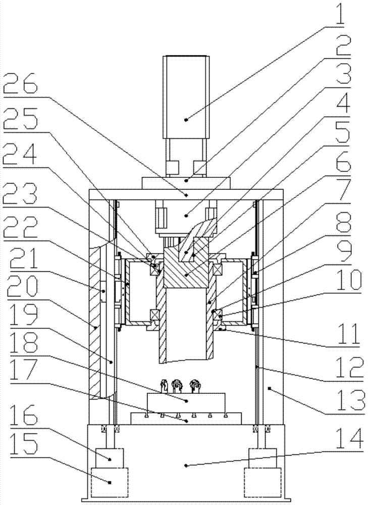
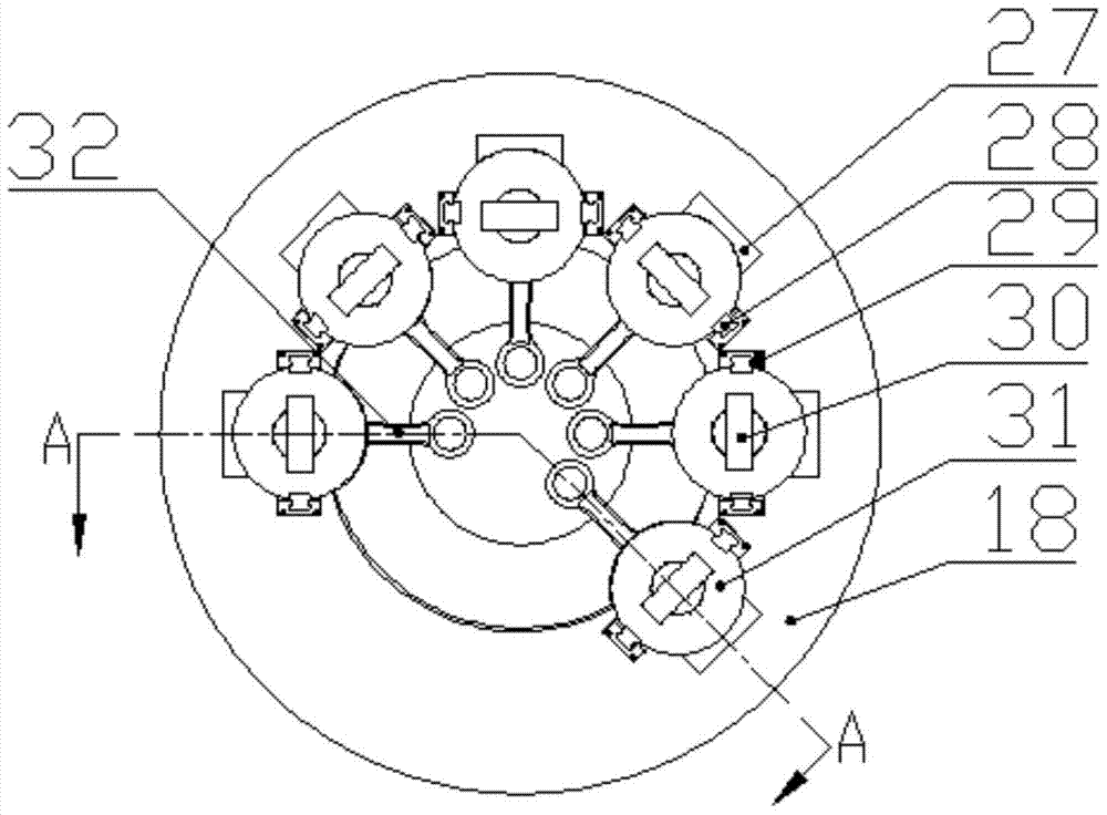
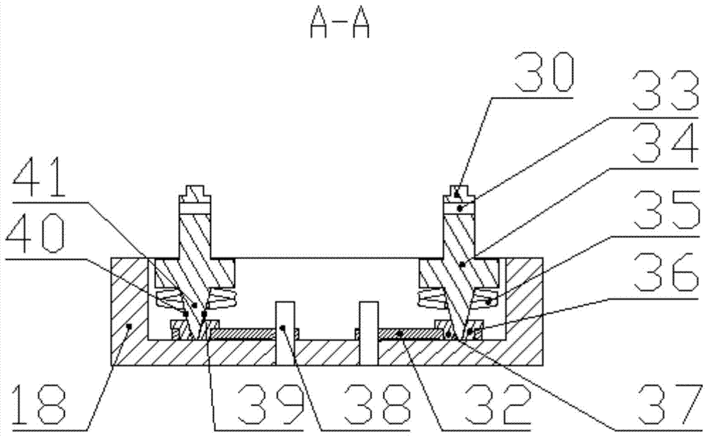

Image

  • Low-cycle fatigue cracking equipment with multi-spindle driven by the end cam of the split connecting rod
  • Low-cycle fatigue cracking equipment with multi-spindle driven by the end cam of the split connecting rod
  • Low-cycle fatigue cracking equipment with multi-spindle driven by the end cam of the split connecting rod

Examples


Embodiment Construction

[0015] The present invention will be further described in detail below in conjunction with the accompanying drawings.

[0016] refer to figure 1 , figure 2 and image 3 , the low-cycle fatigue cracking equipment that the end face cam of the split connecting rod pushes the multi-spindle, including the base 14, the left and right sides of the base 14 are fixedly connected with the first column 20 and the second column 13, the first column 20, the second column The upper side of the two columns 13 is fixedly connected with a crossbeam 26, the motor deceleration power mechanism is connected on the crossbeam 26, the power output of the motor deceleration power mechanism is connected with the power input of the cam lifting mechanism, and the first slider 8 and the first slider 8 connected to the cam lifting mechanism both sides The inner side of the column 20 and the second column 13 is connected with the first guide rail 12 to cooperate. When working, the end face cam 7 of the c...


PUM


Abstract

The end face cam of the split connecting rod pushes the multi-axis low cycle fatigue cracking equipment, including the base, the first and second columns are fixedly connected to the left and right sides of the base, and the upper side of the first and second columns is fixedly connected to the beam , the motor deceleration power mechanism is connected to the beam, the power output of the motor deceleration power mechanism is connected to the power input of the cam lifting mechanism, and the first slider connected to the two sides of the cam lifting mechanism is connected to the inside of the first and second columns to cooperate with the first guide rail. When working, the end cam of the cam lifting mechanism cooperates with the mandrel on the disc-shaped worktable, and the disc-shaped workbench is connected to the base through the T-slot table, and the end-face cam is driven to rotate through the motor deceleration power mechanism, and simultaneously pushes multiple mandrels The expansion sleeve repeatedly loads the big end hole of the connecting rod with the prefabricated cracking groove, and completes the low stress fatigue separation of the connecting rod big end and the connecting rod body. The invention has the advantages of green energy saving, high processing efficiency, wide application range and good cross-section quality advantage.

Description

technical field [0001] The invention belongs to the technical field of cracking processing of connecting rods, and in particular relates to low-cycle fatigue cracking equipment in which end cams of split connecting rods push multi-spindle shafts. Background technique [0002] Connecting rod cracking is a new process of connecting rod processing. Using the theory of fracture mechanics, firstly, a cracking groove is prefabricated inside the big end hole of the connecting rod to form an initial crack, and then a radial force is applied to the inner surface of the big end hole through the cracking processing equipment to make the crack Expand outward from the inner hole until it is completely cracked. Finally, the connecting rod body and the end cover are fully engaged at the fractured surface, and the bolts are inserted and tightened to the required torque. Typical cracking processing equipment includes the "upper wedge" equipment of the German ALFING company and the "pull-down...

Claims


Application Information

Patent Timeline
Patent Type & Authority Patents(China)
IPC IPC(8): B23P17/02
CPCB23P17/02
Inventor 赵升吨董渊哲景飞任芋见
Owner XI AN JIAOTONG UNIV
Learn More