
Landing-gear raising-lowering device

A retractable device and landing gear technology, applied to the chassis and other directions, can solve the problems of reduced payload installation, different structural principles, and large sweeping space, so as to reduce system complexity, simplify the retractable system, and save storage space Effect

Active Publication Date: 2016-01-20
LANDING GEAR ADVANCED MFG
View PDF7 Cites 17 Cited by
  • Summary
  • Abstract
  • Description
  • Claims
  • Application Information

AI Technical Summary

Problems solved by technology

The traditional hydraulic (pneumatic) pressure retractable system accounts for a large proportion of the landing gear of small aircraft and UAV, and the structural space is relatively large, which greatly limits the performance and weight requirements of the landing gear.
[0004] Chinese patent CN200910041370.9 discloses a model aircraft electric retractable landing gear, although this kind of landing gear also adopts electric retractable form, but the structure principle is completely different from the present invention, and is not suitable for the present invention
[0006] 2) For small aircraft with a narrow fuselage, many landing gears are arranged in a splayed shape, and its structure takes up more space. In the process of stowing, the structure described above cannot move in a plane, resulting in a large space for sweeping in the cabin , making the undercarriage bay larger, will reduce the payload installation
[0009] 5) The above-mentioned patents are locked in the closed position due to figure 2 The above-mentioned 6 is a flexible device, which may vibrate up and down when the landing gear encounters shock, vibration and overload conditions, causing damage to the landing gear and other structures or devices in the landing gear compartment

Method used


Image

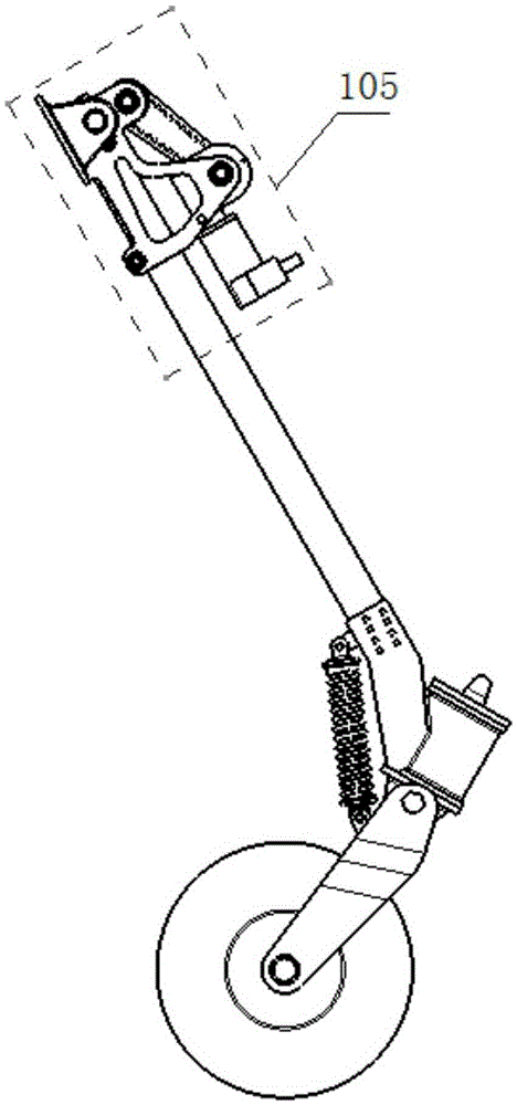
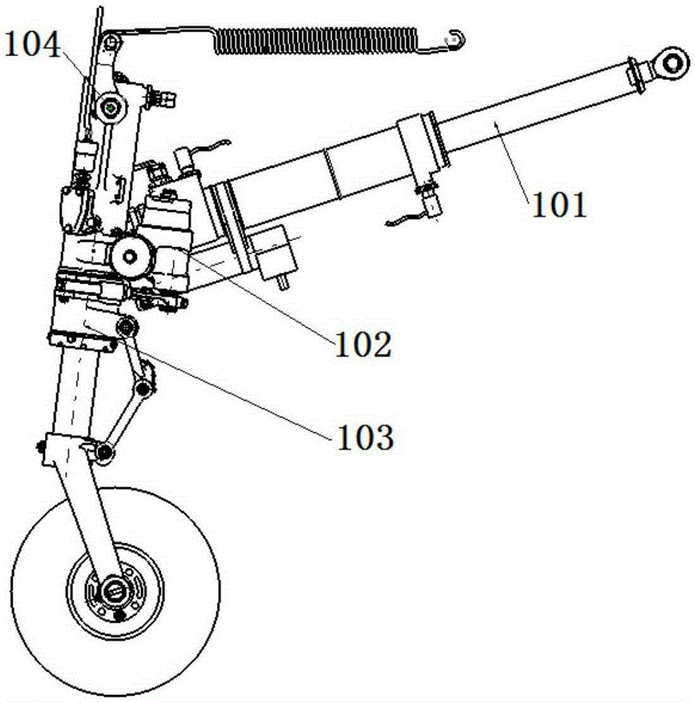
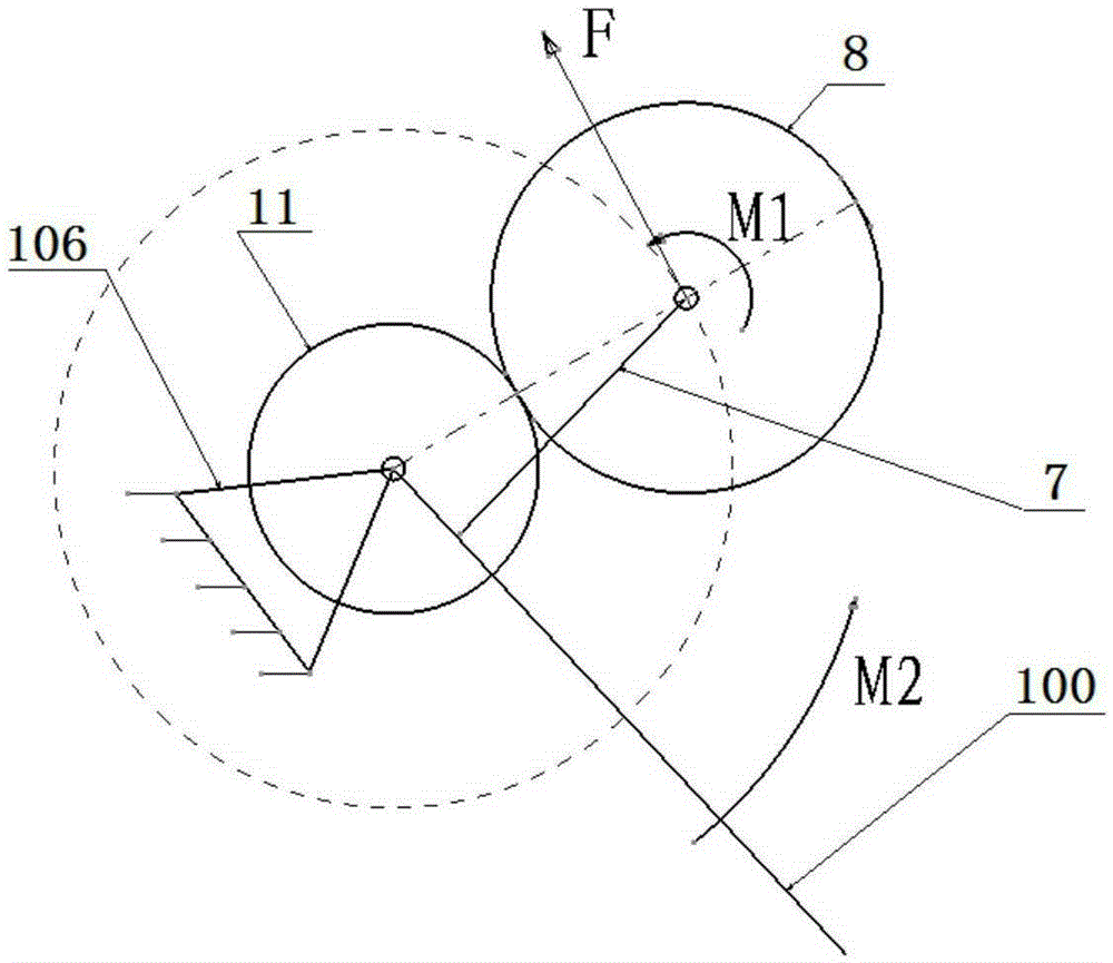
  • Landing-gear raising-lowering device
  • Landing-gear raising-lowering device
  • Landing-gear raising-lowering device

Examples


Embodiment Construction

[0042] A landing gear electric retractable device, such as Figure 4, 5, including motor 2, turbine 4, worm 3, timing belt 6, bracket 7, gear 8, axle 12, mounting base 13 and so on. The motor is mounted on the bracket through screws, and the motor shaft is connected with the worm through key teeth; the two ends of the worm are installed in the worm cover and connected with the motor through a keyway; one end of the worm shaft is a worm gear and the other end is a gear , the two ends of the shaft are installed on the bracket, the turbine is installed in the turbine cover and meshed with the worm, and the gear is connected with the timing belt; one end of the timing belt is installed on the tooth of the timing belt of the turbine shaft, and its The other end is mounted on the gear; the gear is composed of two large and small gears, the large gear meshes with the synchronous belt, the pinion meshes with the sector gear, and is installed on the bracket through bolts; the sector ge...


PUM


Abstract

The invention discloses a landing-gear raising-lowering device. The raising-lowering device comprises a support used for being fixedly connected with a landing gear. A shaft hole is formed in the support. A wheel shaft used for being fixedly connected with an aircraft body is installed in the shaft hole. A sector gear is fixedly installed on the wheel shaft. A worm and gear mechanism driven by a driving mechanism is installed in the support. A worm gear tooth and a synchronous belt gear tooth are arranged on a worm gear shaft of the worm and gear mechanism. The synchronous belt gear tooth is engaged with a gear in a transmission mode through a synchronous belt to form a synchronous belt gear mechanism. The gear fixedly connected with the support is engaged with the sector gear in a transmission mode. The landing-gear raising-lowering device has the advantages that the structure and the functions are integrated, control is easy, working performance is stable and reliable, the manufacturing technology is simple, and maintenance is easy; the requirements for modern small aircraft landing-gear raising-lowering devices are met.

Description

technical field [0001] The invention relates to a landing gear retractable device, which belongs to an actuator device of an aircraft landing gear turning system, and is especially applicable to the electric retractable system structure of a small aircraft and an unmanned aerial vehicle. Background technique [0002] The landing gear retractable system mainly realizes the retractable and retractable landing gear, the upper and lower locking functions, and the ground sliding support landing gear function. The retraction and retraction of the landing gear of the traditional small aircraft mainly converts the high-pressure oil (gas) of the hydraulic and pneumatic energy systems into linear motion through the retractable actuator and the upper and lower position locks to realize the functions of retracting and extending the landing gear and locking the upper and lower positions. In order to realize the retractable locking function, complex hydraulic (gas) pressure source devices...

Claims


Application Information

Patent Timeline
IPC IPC(8): B64C25/24B64C25/26
Inventor 张威金军慕建全吴林孙继勇折世强李田囡马驰
Owner LANDING GEAR ADVANCED MFG
Learn More