
Grain elevator with multilevel treatment function

A grain suction machine and fan technology, which is applied to conveyors, transportation and packaging, conveying bulk materials, etc., can solve the problems of environmental pollution, inconvenient control methods, and reduce the service life of grain suction machines. space saving effect

Inactive Publication Date: 2016-01-20
HUNAN LEIGENG LIGHT TILLAGE MACHINE MFG CO LTD
View PDF5 Cites 7 Cited by
  • Summary
  • Abstract
  • Description
  • Claims
  • Application Information

AI Technical Summary

Problems solved by technology

[0002] Nowadays, with the development of science and technology, people have higher and higher requirements for various equipment. The traditional grain suction machine has inconvenient control methods, and the control of different modules is relatively scattered, thus reducing the use efficiency of the grain suction machine. , the traditional grain suction machine, it is easy to generate a lot of dust when it is used, pollute the use environment, and also cause damage to the machinery inside the grain suction machine, thus reducing the service life of the grain suction machine and the working quality of the grain suction machine

Method used


Image

  • Grain elevator with multilevel treatment function
  • Grain elevator with multilevel treatment function

Examples


Embodiment 1

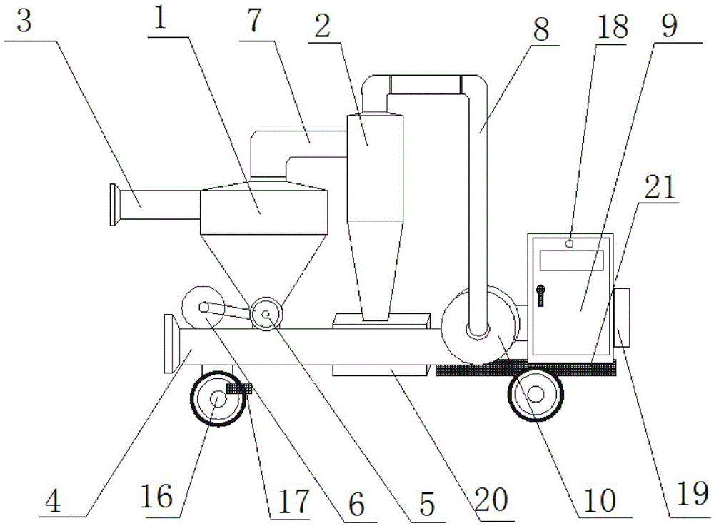
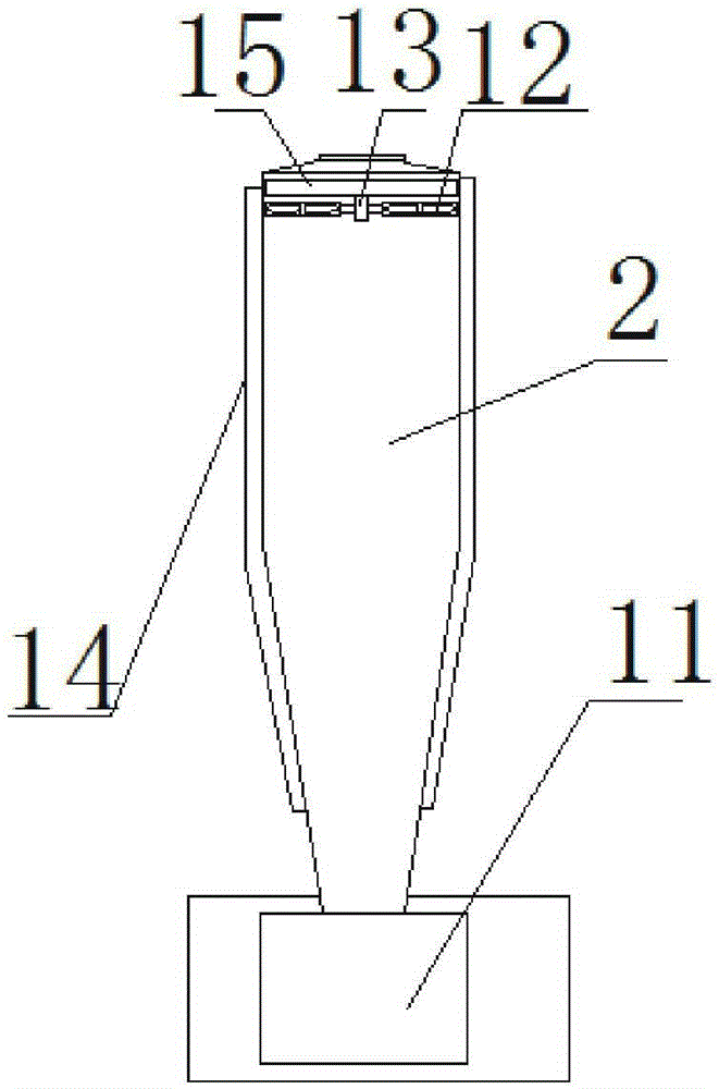
[0022] Such as figure 1 and figure 2 As shown, the bottom of the dust removal chamber 2 is provided with a dust collection box 20 , and the bottom of the dust collection box 20 is provided with a briquetting machine 11 .

[0023] In the present invention, the dust from the dust removal chamber 2 can be collected through the dust collection box 20 to facilitate subsequent processing, and the dust in the dust collection box 20 can be briquetted through the briquetting machine 11, thereby saving collection The space of the dust box 20 is large and convenient to handle the dust.

Embodiment 2

[0025] Such as figure 1 and figure 2 As shown, the inside of the dust removal chamber 2 is provided with a fan 12, the fan 12 is fixedly mounted on the rotating shaft 13, one side of the rotating shaft 13 is fixedly connected to the turntable 15, and the dust removal chamber 2 is provided with a separation layer 14, The bottom of the separation layer 14 is fixedly connected with the discharge pipe 4 .

[0026] In the present invention, the spiral wind can be generated in the dust removal chamber 2 through the work of the fan 12, the rotating shaft 13 and the rotating disk 15, so as to realize the dust removal function of the dust removal chamber 2, and through the separation layer 14, it can be aligned in the dust removal chamber 2. The grain thrown out is collected to prevent it from entering the dust box 20 and causing waste.

Embodiment 3

[0028] Such as figure 1 As shown, the bottom of the discharge channel 4 and the bearing plate 21 are provided with rollers 16, and roller holders 17 are fixedly installed on the rollers 16.

[0029] In the present invention, the roller 16 can be fixed by the roller fixer 17, so as to prevent the grain suction machine from moving during use and affecting the use of the grain suction machine.


PUM


Abstract

The invention provides a grain elevator with the multilevel treatment function and relates to the technical field of agricultural equipment. The grain elevator comprises a separation barrel, a dust removal chamber and a control chamber. A feed port is formed in one side of the separation barrel, and an air-lock valve is fixedly connected with the bottom of the separation barrel. An electromotor is arranged on one side of the air-lock valve, and a discharging channel is fixedly connected with the bottom of the air-lock valve. The separation barrel and the dust removal chamber are fixedly connected through a conveying pipe. A draught fan is arranged on one side of the dust removal chamber. An air guide pipe is fixedly connected between the dust removal chamber and the draught fan. The control chamber is arranged on one side of the draught fan. A bearing plate is arranged at the bottom of the control chamber. According to the grain elevator with the multilevel treatment function, grains can be separated through the separation barrel, and the grains are optimized accordingly; dust from the separation barrel can be treated through the dust removal chamber, and it is guaranteed that outflow air is clean while the grains can not run off; and wind power can be provided for the whole grain elevator through the draught fan, and therefore normal operation of the grain elevator is guaranteed.

Description

technical field [0001] The invention relates to the technical field of agricultural equipment, in particular to a grain suction machine capable of multi-stage processing. Background technique [0002] Nowadays, with the development of science and technology, people have higher and higher requirements for various equipment. The traditional grain suction machine has inconvenient control methods, and the control of different modules is relatively scattered, thus reducing the use efficiency of the grain suction machine. , the traditional grain suction machine, it is easy to generate a lot of dust when it is used, pollute the use environment, and also cause damage to the machinery inside the grain suction machine, thus reducing the service life of the grain suction machine and the working quality of the grain suction machine . Contents of the invention [0003] The technical problem to be solved by the present invention is to provide a grain suction machine capable of multi-st...

Claims


Application Information

Patent Timeline
Patent Type & Authority Applications(China)
IPC IPC(8): B65G53/24B65G53/34
Inventor 任国良
Owner HUNAN LEIGENG LIGHT TILLAGE MACHINE MFG CO LTD
Learn More