Method and system for expediting engine warm-up

An engine and exhaust system technology, applied in the direction of engine starting, engine components, combustion engines, etc., can solve problems such as limiting heat, fuel economy defects, and deteriorating engine knock limit.

Active Publication Date: 2016-01-20
FORD GLOBAL TECH LLC
View PDF12 Cites 2 Cited by
  • Summary
  • Abstract
  • Description
  • Claims
  • Application Information

AI Technical Summary

Problems solved by technology

[0004] However, such methods have the problem of requiring dedicated heaters, which can increase component complexity and cost
Additionally, operation of the heater can lead to fuel economy deficiencies
Furthermore, the heating of the intake manifold air may worsen the knock limit of the engine and reduce the maximum power output of the engine
In systems that rely on heat exch...

Method used


Image

  • Method and system for expediting engine warm-up
  • Method and system for expediting engine warm-up
  • Method and system for expediting engine warm-up

Examples


Embodiment Construction

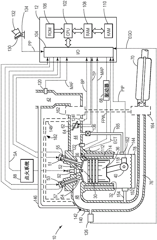
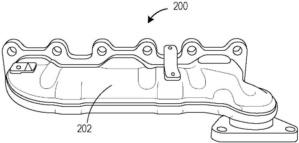
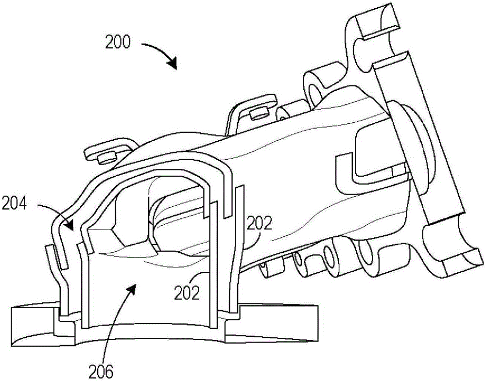
[0019] This application describes a method for heating an engine system such as, figure 1 A method and system for a crankcase in an engine system). As the exhaust circulates through a double wall exhaust system such as, Figure 2-3 In the interstitial space of the exhaust system shown in ), heat from the exhaust can heat the intake air. Intake air in a naturally aspirated engine may be drawn into the interstitial space upstream of the intake throttle ( Figure 4 ). In a forced conduction engine, intake air can be drawn from downstream of the compressor ( Figure 5 ) and upstream of the intake throttle are drawn into the clearance space. Alternatively, intake air heated via the compressor can heat the crankcase ( Figure 6 ) without heating via the interstitial space. The controller can be configured to execute programs such as, Figure 7 program) to flow intake air through the crankcase and adjust fuel injection and / or throttle position based on the amount of crankcase ...


PUM


Abstract

The invention relates to a METHOD AND SYSTEM FOR EXPEDITING ENGINE WARM-UP. Methods and systems are provided for improving crankcase ventilation by directing heated air to a crankcase. Air is drawn into the crankcase upon passage through an interstitial space of a double walled exhaust manifold where it is heated. Crankcase vapors are then released to the engine intake, downstream of an intake throttle.

Description

technical field [0001] The present invention relates to accelerating engine warm-up through the use of heated positive crankcase ventilation. Background technique [0002] During cold start conditions, the vehicle's engine and driveline may have cooled to ambient temperature. Therefore, every component in the engine and driveline needs to be heated to the desired operating temperature. The time it takes to overcome the low drive train temperature and reach the optimum operating temperature can be considerable. When the engine is warm, there may be high friction in the engine due to the higher viscosity of engine fluids (such as engine oil) when it is relatively cold, and further, heat may be lost to the engine coolant, reducing the engine's Thermal efficiency. Together, these effects can lead to lower fuel economy, increased engine wear, and increased exhaust emissions. Thus, accelerating engine warm-up can provide various benefits. [0003] Various methods have been de...

Claims


Application Information

Patent Timeline
IPC IPC(8): F02M31/08F02M35/10F02B77/08
CPCF02D41/06F02D41/064F01N13/102F02D41/22F01M13/02F01M13/028F02D37/02F01M2013/0472F02D2250/08F01M13/00F01N5/02F02D41/0002F01M2013/0038Y02T10/12Y02T10/40F02N19/02F01N11/00F01N13/08
Inventor R·D·皮尔西弗
Owner FORD GLOBAL TECH LLC
Why Eureka
Try Eureka