Oblique flow and centrifugal combined compressor

A compressor and oblique flow pressure technology, applied in the field of compressors, can solve the problems of low efficiency of combined compressors, axial lengthening of the rotor system, unstable rotor dynamics, etc., and achieve excellent rotor dynamics characteristics and large angle folding. Rotation reduction, compact effect

Inactive Publication Date: 2016-01-20
CHINA AVIATION POWER MACHINE INST
View PDF4 Cites 7 Cited by
  • Summary
  • Abstract
  • Description
  • Claims
  • Application Information

AI Technical Summary

Problems solved by technology

[0005] The disadvantages of the above two solutions are: figure 1 In the first type of solution shown, including the diagonal flow compressor 101, the centrifugal compressor 102 and the reflux device 103, the axial length of the combined compressor is too long, which will cause the axial length of the rotor system of the entire compressor to be lengthened, thereby bringing rotordynamic instability
figure 2 The second type of solution shown includes a diagonal flow compressor 201, a centrifugal compressor 202, and a reflux device 203. In order to overcome the technical defects of the first solution, an ultra-compact S-shaped reflux device 203 is adopted to shorten the axial length. , but lead to the complexity of the entire flow channel structure, the air flow repeatedly turns at a large angle in the compact reflux device 203 channel, and the aerodynamic loss is relatively large. Since the efficiency of the centrifugal compressor 202 is usually low, it leads to the overall combined compressor. low efficiency
In addition, the common feature of the above two schemes is that the inclined angles of the outlets of the oblique flow impellers of the oblique flow compressors 101 and 201 are both about 40°. Such an aerodynamic layout makes the above two schemes only applicable to oblique impellers with medium and low pressure ratios. flow compressor, making it difficult for the entire combined compressor to apply to a higher pressure ratio range

Method used


Image

  • Oblique flow and centrifugal combined compressor
  • Oblique flow and centrifugal combined compressor
  • Oblique flow and centrifugal combined compressor

Examples


Embodiment Construction

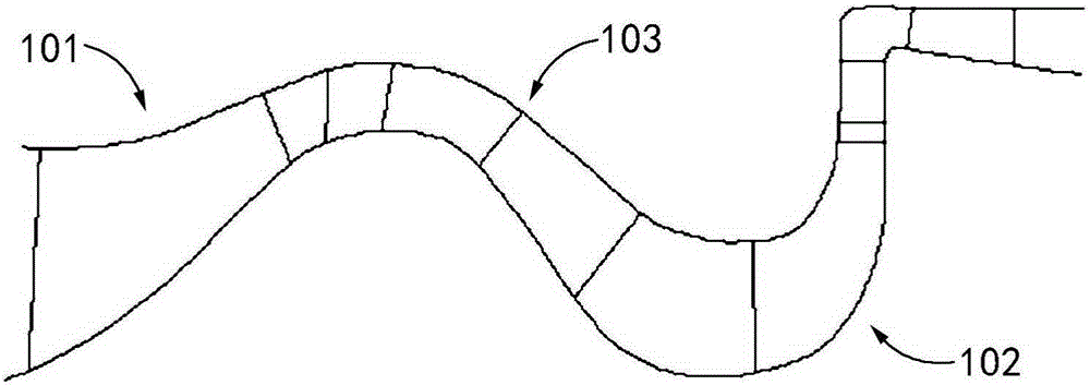
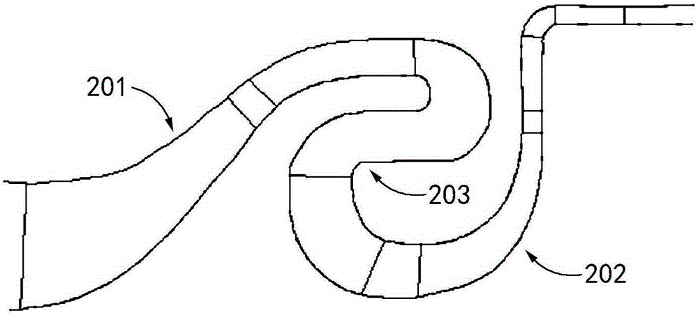
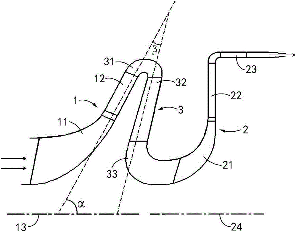
[0027] In the following description of the invention, reference is made to the accompanying drawings, which form a part hereof, and in which are shown by way of illustration different exemplary structures, systems or steps which may implement aspects of the invention. It is to be understood that other specific arrangements of components, structures, exemplary devices, systems and steps may be utilized and structural and functional modifications may be made without departing from the scope of the present invention. Moreover, although the terms "front side," "inflow," "outflow," "axial," etc. may be used in this specification to describe various exemplary features and elements of the invention, these terms are used herein only for Convenience, for example, according to the directions of the examples described in the attached drawings. Nothing in this specification should be construed as requiring a particular three-dimensional orientation of structures in order to fall within th...


PUM


Abstract

The invention discloses an oblique flow and centrifugal combined compressor. The oblique flow and centrifugal combined compressor comprises an oblique flow compressor, a centrifugal compressor and a backflow device. The backflow device is in a gooseneck shape and is connected between the oblique flow compressor and the centrifugal compressor. The backflow device comprises a backflow device curve section channel, a backflow device blade and a backflow device slewing section channel which are connected in sequence. An inlet of the backflow device curve section channel is connected with an outlet of an oblique flow diffuser. The backflow device curve section channel is in an arc shape, so that the backflow device blade is close to the front side of the oblique flow diffuser, and an outlet of the backflow device slewing section channel is connected with an inlet of a centrifugal impeller. On the basis that the axial length of the oblique flow and centrifugal combined compressor is shortened, the whole flow channel structure is simplified, large-angle turns of airflow in the backflow device channels are decreased, pneumatic loss is small, and then the overall efficiency of the combined compressor is improved. Moreover, the axial length of the combined compressor is further shortened, and the oblique flow and centrifugal combined compressor is more compact in structure and has more excellent rotor dynamic characteristics.

Description

technical field [0001] The invention relates to the technical field of compressors, in particular to a large-flow compact oblique-flow centrifugal combined compressor. Background technique [0002] The oblique flow centrifugal combined compressor is a type of combined compressor between the performance of the axial flow centrifugal compressor and the two-stage centrifugal compressor. Compared with the axial flow centrifugal combined compressor, it has a higher single-stage pressure ratio and fewer parts Compared with the two-stage centrifugal compressor, it has the characteristics of large flow and high efficiency. Therefore, the oblique flow centrifugal combined compressor has become a hotspot in the development of combined compressors. [0003] The existing mixed-flow centrifugal combined compressor generally includes two stages, the first stage (inlet stage) is a diagonal-flow compressor, and the second stage (export stage) is a centrifugal compressor. As an inlet-level...

Claims


Application Information

Patent Timeline
Patent Type & Authority Applications(China)
IPC IPC(8): F04D25/16F04D29/40F04D29/26
Inventor 黄生勤杨元英温泉杨晶晶邬国凡王国文邹学奇安志强
Owner CHINA AVIATION POWER MACHINE INST
Why Eureka
Try Eureka