Novel all-welding plate shell type heat exchanger

An all-welded, plate-and-shell technology, applied in the direction of indirect heat exchangers, heat exchanger types, heat exchange equipment, etc., can solve the problems of increasing unilateral fluid disturbance, increasing heat exchange efficiency, complex impermeability, etc., to achieve High energy recovery utilization rate, increased heat exchange area, and flexible and changeable structure

Inactive Publication Date: 2016-01-20
ATHCO ENG SHANGHAI CO LTD
View PDF17 Cites 2 Cited by
  • Summary
  • Abstract
  • Description
  • Claims
  • Application Information

AI Technical Summary

Problems solved by technology

[0003] At present, the most mature heat exchanger type is the shell-and-tube heat exchanger. On the basis of the conventional shell-and-tube heat exchanger, innovations such as spiral fluted tube heat exchangers, insert heat exchangers in tubes, and baffles have emerged. Rod heat exchangers, tube-fin heat exchangers and other new types, their main principle is to increase the heat exchange efficiency by increasing the turbulence of the fluid on one side, while improving the heat exchange efficiency, the pressure drop is greatly increased, and it is complicated. The transparent structure is not easy to clean; in addition, the plate and shell heat exchanger is a more efficient device, including the heat exchange plate and the shell with grooves, the shell acts as a pressure vessel, and the channels on both sides are small. As a result, the fluid on both sides is disturbed. It has the characteristics of high heat exchange efficiency, small heat loss, compact structure, and small footprint. Compared with rubber-containing gasketed plate heat exchangers, it can withstand higher Pressure and corrosion resistance, but in order to achieve high heat exchange efficiency, the gap between the plates is very small, and it contains contacts, which is very inconvenient to clean, so this type of heat exchanger is limited to be used for both sides of the medium very clean workplace

Method used


Image

  • Novel all-welding plate shell type heat exchanger
  • Novel all-welding plate shell type heat exchanger
  • Novel all-welding plate shell type heat exchanger

Examples


Embodiment 1

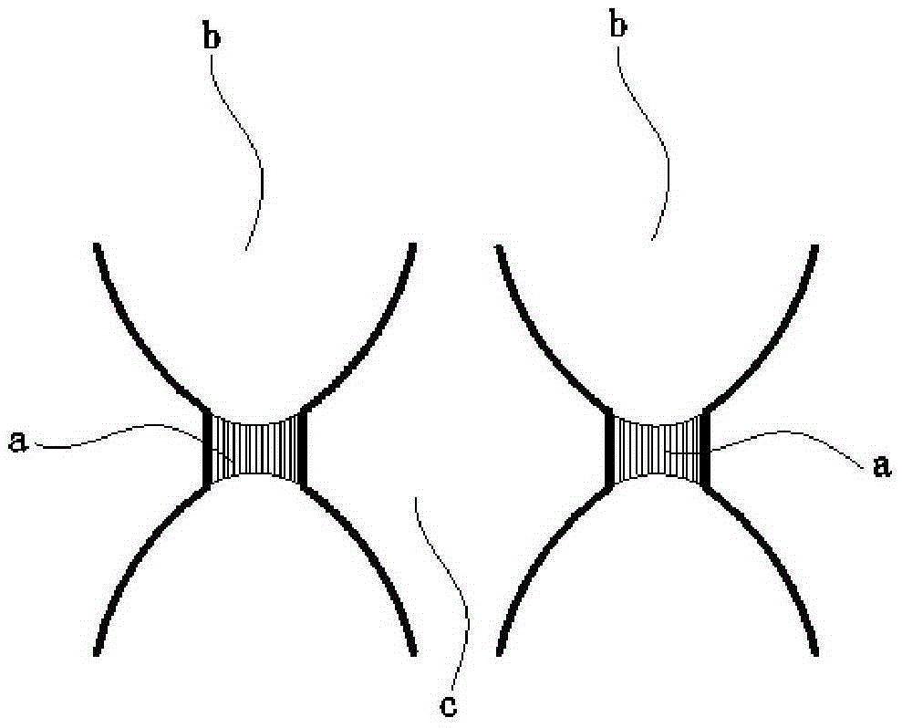
[0047] Such as Figure 4 As shown, a new type of fully welded plate and shell heat exchanger includes a shell 1, a heat exchange plate pair body 7, and a plate-side heat exchange fluid inlet N1, a plate-side heat exchange fluid outlet N2, Shell side heat exchange fluid inlet N3, shell side heat exchange fluid gas phase outlet N4 and shell side heat exchange fluid liquid phase outlet N5. The heat exchange plate pair main body 7 is installed in the housing 1, and is composed of the heat exchange plate pair 3, such as figure 1 As shown, the heat exchange plate pair 3 is composed of two metal plates by welding a plurality of contacts to form a plate side cavity b for the circulation of the plate side heat exchange fluid. Between each heat exchange plate pair 3 and the housing 1 forms a shell-side cavity c for the circulation of the shell-side heat exchange fluid. In the heat exchange plate pair 3, the contact welding method is that the welding contact welding method is spot weld...

Embodiment 2

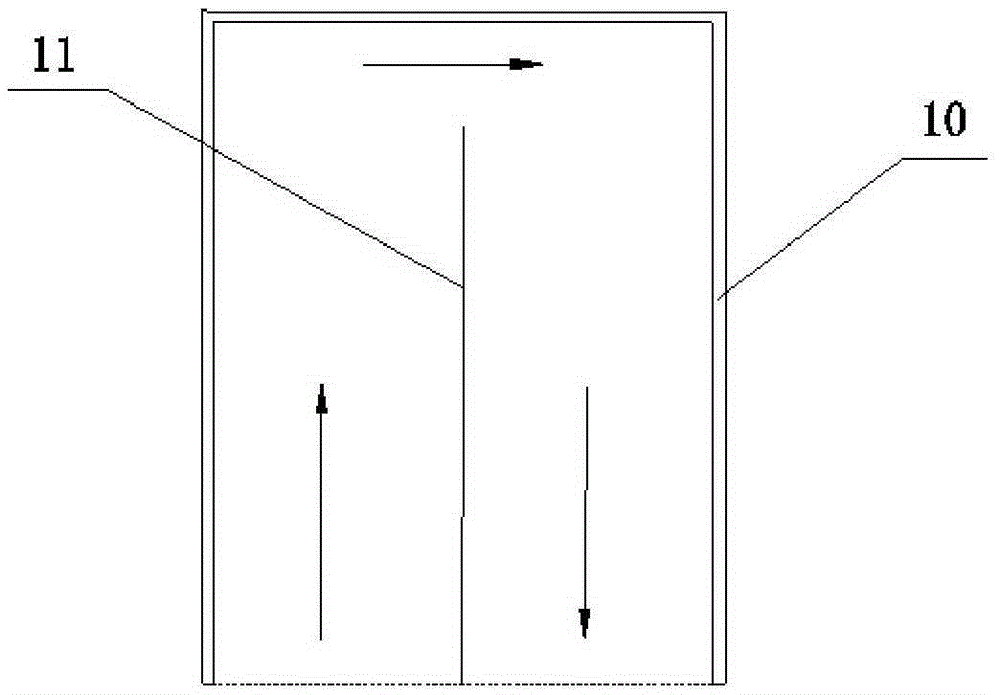
[0058] Such as Figure 8 As shown, in this embodiment, the heat exchange plate pair main body 7 of the new all-welded plate and shell heat exchanger is a cuboid structure, and the cuboid structure is formed by parallel arrangement of multiple pairs of square heat exchange plate pairs 3 of the same size. , the heat exchange plate pairs forming the plate bundle have the same size, the heat exchange fluid in the plate side enters the plate side cavity b through the heat exchange fluid connection pipe 12 in the plate side, and the heat exchange fluid in the shell side can be selected from Entering the shell-side cavity c in any direction can realize counter-current, forward-current and cross-flow heat exchange.

[0059] All the other are identical with embodiment 1.

Embodiment 3

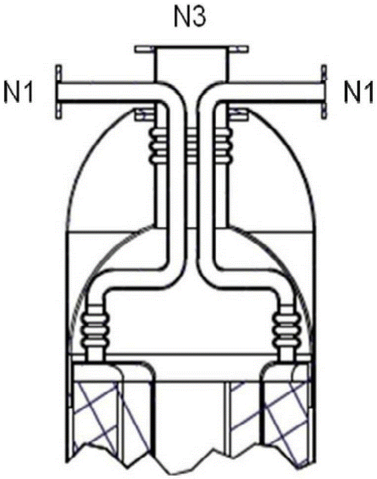
[0061] Such as Figure 6 , Figure 7 As shown, in this embodiment, the main body 7 of the heat exchange plate pair is a spiral cylindrical structure, and the said spiral cylindrical structure is a pair of coiled plate heat exchange plate pairs 3 with a spiral cross-section, which are cylindrical as a whole. In the spiral cylinder structure, the outer edges of the two ends of the pair of heat exchange plates 3 are provided with tongues, and the pair of heat exchange plates 3 is fixed on the shell 1 through the positioning holes on the tongues. The plate-side heat exchange fluid enters from the plate-side heat-exchange fluid inlet N1, flows through the plate-side chamber b of the entire heat exchange plate pair 3, and exits from the plate-side heat-exchange fluid outlet N2. The shell-side heat exchange fluid enters axially from the shell-side heat exchange fluid inlet N3, and flows axially through the entire shell-side space; or enters from the center, flows out from the edge, ...


PUM


Abstract

The invention relates to a novel all-welding plate shell type heat exchanger. The novel all-welding plate shell type heat exchanger comprises a shell (1), a heat exchange plate pair body (7), a plate pass heat exchange fluid inlet, a plate pass heat exchange fluid outlet, a shell pass heat exchange fluid inlet, a shell pass heat exchange fluid gas phase outlet and a shell pass heat exchange fluid liquid phase outlet, wherein the plate pass heat exchange fluid inlet, the plate pass heat exchange fluid outlet, the shell pass heat exchange fluid inlet, the shell pass heat exchange fluid gas phase outlet and the shell pass heat exchange fluid liquid phase outlet are formed in the shell (1); the heat exchange plate pair body (7) is installed in the shell (1) and formed by heat exchange plate pairs (3), each heat exchange plate pair (3) forms a plate pass cavity by welding a plurality of contacts on two metal plates, and the plate pass cavities allow plate pass heat exchange fluid to circulate therein; shell pass cavities are formed between the heat exchange plate pairs (3) and between the heat exchange plate pairs (3) and the shell (1) and allow shell pass heat exchange fluid to circulate therein; and the heat exchange plate pair body (7) is of one of a cuboid structure, a cylinder structure or a spiral cylinder structure. Compared with the prior art, the novel all-welding lamella heat exchanger has the beneficial effects of being high in heat exchange efficiency, small in land occupation, flexible and changeable in structure, large in heat exchange area, compact in heat exchange system and low in pressure reduction.

Description

technical field [0001] The invention relates to a plate-shell heat exchanger, in particular to a novel all-welded plate-shell heat exchanger. Background technique [0002] Heat exchanger is a very important heat exchange equipment, which realizes the heat transfer between various media at different temperatures. It can greatly improve the utilization rate of energy, and is widely used in petroleum, chemical industry, metallurgy, electric power, Refrigeration and food industries. With the rapid growth of energy demand, the industrial scale of various industries is also gradually expanding, which brings challenges to various equipment. For the same working conditions, after the scale increases, the equipment will also increase at the same time, which in turn will bring about A series of difficulties such as land, manufacturing, installation and maintenance. Therefore, how to substantially increase the heat exchange efficiency of the heat exchanger is an important subject. ...

Claims


Application Information

Patent Timeline
Patent Type & Authority Applications(China)
IPC IPC(8): F28D9/00F28F3/04
Inventor 李凤清傅建敏
Owner ATHCO ENG SHANGHAI CO LTD
Why Eureka
Try Eureka