

Method and device for shielding weather interference in fiber monitoring alarm system
An alarm system and weather technology, applied in the direction of alarm, anti-theft alarm, anti-theft alarm mechanical start, etc., can solve the problems of monitoring efficiency and accuracy that need to be improved
Active Publication Date: 2016-01-20
湖南讯美智能科技有限公司
View PDF5 Cites 12 Cited by
- Summary
- Abstract
- Description
- Claims
- Application Information
AI Technical Summary
Problems solved by technology
However, due to the different values of short-term energy ratio and short-term zero-crossing rate calculated by different intensities of climate (such as heavy rain and light rain), it is necessary to adjust the upper and lower limits at any time according to weather changes, so the monitoring efficiency of this method and Accuracy needs to be improved
Method used
View moreImage
Smart ImageViewing Examples

Examples
Embodiment 1
[0047] Such as Figure 1-7 , a method for shielding weather interference in an optical fiber monitoring and alarm system, is characterized in that, comprising the following steps:
Login to View More PUM
 Abstract
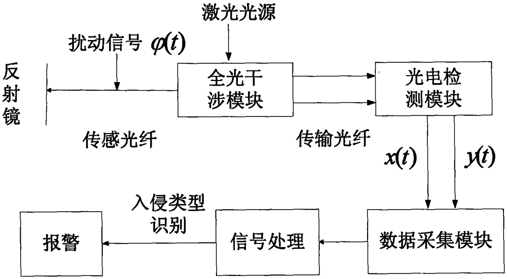
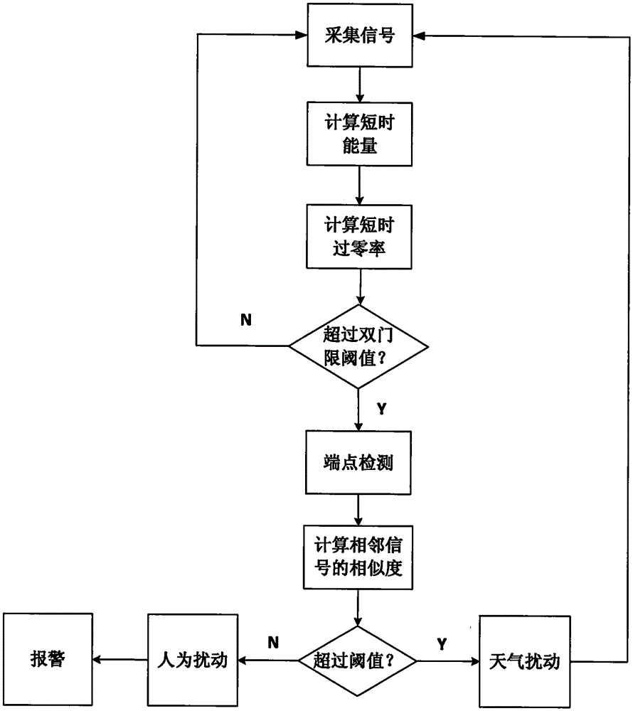
The invention discloses a method and device for shielding weather interference in a fiber monitoring alarm system. The method comprises the following steps: step1, performing endpoint detection of disturbing signals by adopting a method of short-time energy and short-time zero-crossing rate to detect an initial point and an end point of an effective signal; step2, performing calculation of a Pearson product-moment correlation coefficient of effective signals lambda1 and lambda1, which are monitored by two sensors separated at a certain distance, and determining the disturbing signal, the Pearson product-moment correlation coefficient of which is higher than the upper coefficient threshold CH, as a weather disturbing signal; and determining the disturbing signal, the Pearson product-moment correlation coefficient of which is lower than the lower coefficient threshold CL, as an invasion signal, and sending put an alarm. The method and device for shielding weather interference in the fiber monitoring alarm system is high in monitoring efficiency and accuracy, and is easy to apply.
Description
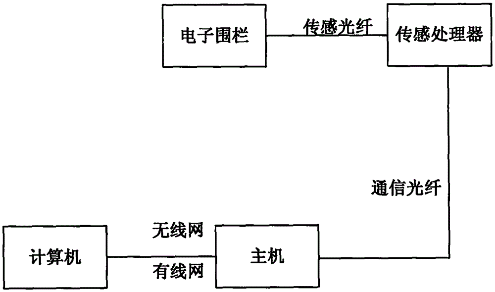
technical field [0001] The invention relates to a method and device for shielding weather interference in an optical fiber monitoring and alarm system. Background technique [0002] Optical fibers are very sensitive to external environmental factors. Changes in environmental conditions such as temperature, pressure, electric field, and magnetic field will cause changes in light wave parameters (such as intensity, phase, frequency, polarization state, etc.). According to the changes of these parameters, the optical fiber sensor can know the size of physical quantities such as temperature, pressure, electric field, and magnetic field that cause the changes of these light wave parameters. In addition, the optical fiber sensor also has the characteristics of small size, light weight, anti-electromagnetic interference, high sensitivity, and easy networking, and the optical fiber itself is passive, does not require external power supply, and can also be used as a signal transmissi...
Claims
Login to View More Application Information
Patent Timeline
 Patent Type & Authority Applications(China)
IPC IPC(8): G08B13/12G08B29/18
CPCG08B13/124G08B29/185
Inventor 陈英王路露张竹娴周晓霞夏旭
Owner 湖南讯美智能科技有限公司