Supercharge Your Innovation With Domain-Expert AI Agents!

Power Rope Launcher

A launcher and rope technology, which is applied in the direction of overhead lines/cable equipment, etc., can solve the problems of reduced launch accuracy, large wind surface of the anchor hook, small target, etc., to save working time, have accuracy, and improve accuracy Effect

Inactive Publication Date: 2017-04-19
DONGYING POWER SUPPLY COMPANY STATE GRID SHANDONG ELECTRIC POWER +2
View PDF12 Cites 1 Cited by
  • Summary
  • Abstract
  • Description
  • Claims
  • Application Information

AI Technical Summary

Problems solved by technology

[0002] At present, during the construction of power poles and towers or in the process of line maintenance and repair, construction workers often need to climb tens of meters high poles or poles to a sufficient height for power lines to carry out work. Common climbing tools are portable climbing tools. Pedals, during the climbing process, it is necessary to fix the teaching pedals on the feet, and fix the safety belt around the waist to avoid accidents. It is very hard and tiring to use, and the maintenance personnel are prone to fatigue, which is not convenient for long-term work.
Moreover, on the high-voltage transmission lines in mountainous areas, construction workers need to climb up the power tower and then walk on the high-voltage lines in order to overhaul the high-voltage lines, which is very dangerous and inconvenient
[0003] At present, in the field of emergency rescue or military use, the application of rope shooting guns has been very popular. There is no public technical attempt to apply rope shooting guns to the field of electric climbing. Unlike buildings such as walls or mountains, the guy wires have smaller targets and cannot be directly hung on the anchor hook
In addition, the rope used by the rope shooting gun is relatively thick, the anchor hook has a large wind surface, and the recoil force when launching is also large. These three factors all reduce the accuracy of the launch.

Method used


Image

  • Power Rope Launcher
  • Power Rope Launcher
  • Power Rope Launcher

Examples


Embodiment Construction

[0017] The present invention will be further described in detail below in conjunction with the accompanying drawings and specific embodiments.

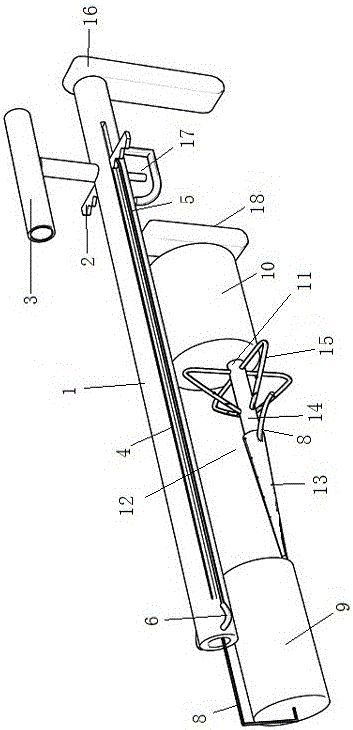
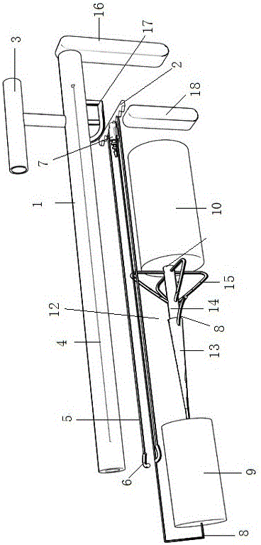
[0018] Such as figure 2 , 3 As shown, the electric rope launcher includes a rope launcher 1 and a sliding bolt 2; the right side of the upper end of the rope launcher 1 is provided with an aiming part 3; The length direction is provided with the guide channel 4 that cooperates with the sliding gun bolt 2; the two sides of the sliding gun bolt 2 are respectively fixed with tension lines 5, and the other ends of each tension line 5 are respectively fixed with pull hooks 6, and the two pull hooks 6 are respectively fixed on the Both sides of the front end of the rope launcher 1; in the cavity of the rope launcher 1, the front side of the sliding gun bolt 2 is provided with an inertial traction bullet 7, and the rear end of the inertial traction bullet 7 is fixed with an insulated pull wire 8; the insulated pull wire 8 wears The cavity...


PUM


Abstract

The present invention discloses an electric power rope emitter, and relates to the technical field of electric power overhaul equipment. The electric power rope emitter comprises a rope emission cylinder and a sliding bolt; wherein the right side of the upper end of the rope emission cylinder is provided with an aiming part; the sidewall of the rope emission cylinder is provided with a guiding straight slot matched with the sliding bolt in the length direction; the front side of the sliding bolt is provided with an inertia traction bullet, the rear end of the inertia traction bullet is fixedly provided with an insulating pull wire; the front end of a climbing wire is provided with a fixed hook; the fixed hook comprises a transition wiring clamp and a center pull rod; the transition wiring clamp is in a circular truncated cone shape, the diameter of the top surface of the transition wiring clamp is the same with the diameter of the insulating pull wire, the bottom of the transition wiring clamp is connected with the center pull rod, and the diameter of the bottom of the transition wiring clamp is the same with the diameter of the center pull rod; the outer wall of the center pull rod is uniformly and fixedly provided with at least four backswept self-locking catches in a circumferential direction; and the rear end of the center pull rod is connected with the climbing wire. The electric power rope emitter of the present invention is simple in structure and convenient in use, can facilitate operation of construction personnel and save operation time of the construction personnel, in addition, the electric power rope emitter is more accurate in emission of an object.

Description

technical field [0001] The invention relates to the technical field of electric power maintenance equipment. Background technique [0002] At present, during the construction of power poles and towers or in the process of line maintenance and repair, construction workers often need to climb tens of meters high poles or poles to a sufficient height for power lines to carry out work. Common climbing tools are portable climbing tools. Pedals, in the climbing process, need to fix the teaching pedals on the feet, and fix the safety belt around the waist to avoid accidents. It is very hard and tiring to use, and the maintenance personnel are prone to fatigue, which is not convenient for long-term work. Moreover, on the high-voltage transmission lines in mountainous areas, construction workers need to climb up the power tower and then walk on the high-voltage lines in order to overhaul the high-voltage lines, which is very dangerous and inconvenient. [0003] At present, in the fi...

Claims


Application Information

Patent Timeline
Patent Type & Authority Patents(China)
IPC IPC(8): H02G1/02
Inventor 杨西建昝乐李钊宋学龙胡永伟刘泽昆
Owner DONGYING POWER SUPPLY COMPANY STATE GRID SHANDONG ELECTRIC POWER
Features
  • R&D
  • Intellectual Property
  • Life Sciences
  • Materials
  • Tech Scout
  • Unparalleled Data Quality
  • Higher Quality Content
  • 60% Fewer Hallucinations
Learn More