Method and apparatus for controlling voltage of flying capacitor in multilevel inverter circuit

A technology of multi-level inverter and floating capacitor, which is applied in output power conversion devices, electrical components, and the conversion of AC power input to DC power output, etc., can solve the problem of increasing switch tube stress and inconvenient switch tube selection. And other issues

Active Publication Date: 2016-01-20
SUNGROW POWER SUPPLY CO LTD
View PDF5 Cites 6 Cited by
  • Summary
  • Abstract
  • Description
  • Claims
  • Application Information

AI Technical Summary

Problems solved by technology

[0004] In the above inverter circuit, the voltage of the first floating capacitor needs to reach a certain value and remain stable during operation. For example, for the first level switching unit 12, the voltage value of the first floating capacitor C1 can be maintained at PV / 4 , where the voltage between the two terminals of PV is the DC power supply voltage value input to the primary capacitor inverter unit 11, at this time, as figure 1 As shown, if the switch tube in the primary capacitor inverter unit 11 is controlled so that the potentials between the two terminals of AP are equal, the voltage between the two terminals of BN is the voltage between the two terminals of the entire PV minus the first floating capacitor C1 The voltage at both ends, that is, 3PV / 4, if the voltage between the two terminals of PV is high, the switching tube set in the primary capacitor inverter unit 11 between the two terminals of NB needs to withstand a large voltage drop; similarly, if BN The voltage between the two terminals is equal, then the voltage between the two terminals of the AP is the voltage between the two terminals of the entire PV minus the voltage of the first floating capacitor C1, that is, 3PV / 4. If the voltage between the two terminals of the PV is higher, Then, the switch tube installed in the primary capacitor inverter unit 11 between the two terminals of the AP bears a large voltage drop, and the large voltage drop will increase the stress of the switch tube, which is not convenient for the selection of the switch tube.

Method used


Image

  • Method and apparatus for controlling voltage of flying capacitor in multilevel inverter circuit
  • Method and apparatus for controlling voltage of flying capacitor in multilevel inverter circuit
  • Method and apparatus for controlling voltage of flying capacitor in multilevel inverter circuit

Examples


Embodiment 1

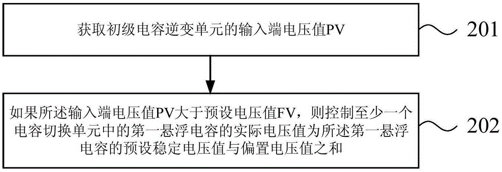
[0036] figure 2 It is a flowchart of a method for controlling the floating capacitor voltage in a multi-level inverter circuit provided by Embodiment 1 of the present invention. This embodiment is applicable to controlling the dynamic adjustment of the floating capacitor voltage in a multi-level inverter circuit , the method can be performed by a device for controlling the floating capacitor voltage in a multilevel inverter circuit, such as figure 2 As shown, this embodiment provides a method for controlling the floating capacitor voltage in a multi-level inverter circuit. The structure of the multi-level inverter circuit can be as follows figure 1 As shown, the method includes the following steps:

[0037] Step 201 , acquiring the input terminal voltage value PV of the primary capacitor inverter unit 11 .

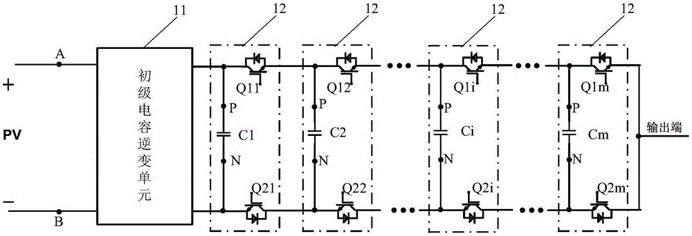
[0038]In this embodiment, the multilevel inverter circuit includes a primary capacitor inverter unit 11 and cascaded m level switch units 12, the input end of the prim...

Embodiment 2

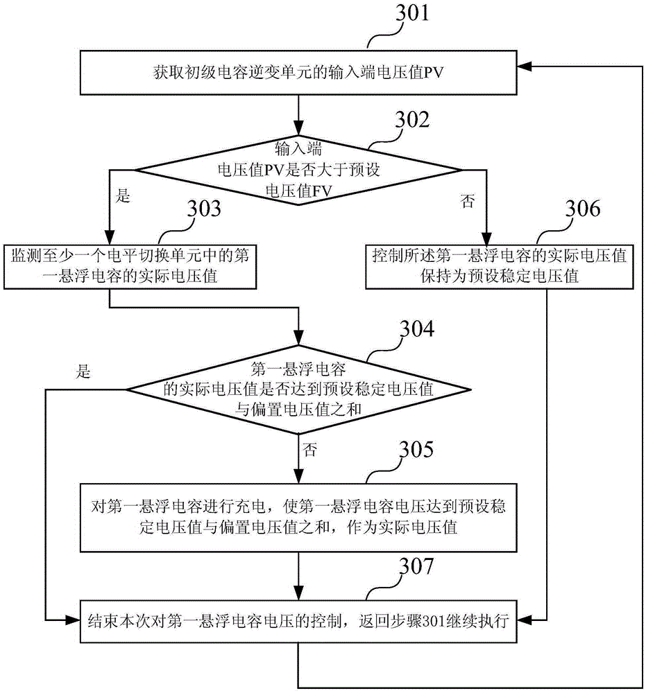
[0051] image 3 It is a flowchart of a method for controlling the floating capacitor voltage in a multi-level inverter circuit provided by Embodiment 2 of the present invention. This embodiment is optimized on the basis of the above-mentioned embodiments. In this embodiment, the steps Controlling the actual voltage value of the first floating capacitor in at least one level switching unit is the sum of the preset stable voltage value and the bias voltage value of the first floating capacitor, which is further optimized to: monitor the at least one level switching The actual voltage value of the first floating capacitor in the unit; if the actual voltage value of the first floating capacitor in the jth level switching unit is lower than the sum of the preset stable voltage value and the bias voltage value, then for the first The floating capacitor is charged so that the actual voltage value reaches the sum of the preset stable voltage value and the bias voltage value.

[0052]...

Embodiment 3

[0074] A method for controlling the floating capacitor voltage in a multilevel inverter circuit provided by the present invention is specifically implemented in a multilevel inverter, by figure 1 It can be seen from the structural schematic diagram of the multilevel inverter circuit that the multilevel inverter includes a primary capacitor inverter unit 11 and m level switching units 12 connected in cascade. Among them, the primary capacitor inverter unit 11 has more implementation structures. Embodiment 3 of the present invention provides several implementations of the primary capacitor inverter unit, which may specifically be Figure 4A , Figure 4B , Figure 4C , Figure 4D , which are only circuit diagrams of four preferred primary capacitor inverter units 11 provided in Embodiment 3 of the present invention.

[0075] see Figure 4A As shown, the primary capacitor inverter unit 11 includes: a second capacitor C00, a third capacitor C01, a third switching tube Q1, a fou...


PUM


Abstract

The embodiment of the invention discloses a method and an apparatus for controlling the voltage of a flying capacitor in a multilevel inverter circuit. The method includes: obtaining the voltage value PV of an input terminal of a primary capacitor inversion unit; and controlling the actual voltage value of a first flying capacitor in at least one level switching unit to be the sum of a preset stable voltage value of the first flying capacitor and a bias voltage value if the voltage value PV of the input terminal is greater than a preset voltage value FV. According to the technical scheme, after the stable voltage of the first flying capacitor of the level switching unit is increased, the stress of switch tubes in a multilevel inverter is reduced, and type selection approaches of the switch tubes are increased.

Description

technical field [0001] Embodiments of the present invention relate to power electronics technology, and in particular to a method and device for controlling the voltage of a floating capacitor in a multilevel inverter circuit. Background technique [0002] The multi-level inverter circuit has the advantages of small output harmonics, fast dynamic response, wide transmission frequency bandwidth, good electromagnetic compatibility, light weight, small size and high efficiency, and is more and more valued by the photovoltaic industry, so that multi-level Inverters are widely used in medium-voltage and large-capacity applications. Such as figure 1 As shown, it is a schematic structural diagram of a multi-level inverter circuit in the prior art, the multi-level inverter circuit includes a primary capacitor inverter unit 11, and cascaded m level switching units 12, m is an integer greater than or equal to 1, wherein the input terminal of the primary capacitor inverter unit 11 is...

Claims


Application Information

Patent Timeline
Patent Type & Authority Applications(China)
IPC IPC(8): H02M7/483
Inventor 耿后来申潭王鹏别伟李浩源
Owner SUNGROW POWER SUPPLY CO LTD
Why Eureka
Try Eureka