Solar thermal-field electron emission power generation device

一种场电子发射、太阳能热的技术,应用在太阳能热发电、热电器件、光伏发电等方向,能够解决发电成本居高不下、转化率低等问题

Inactive Publication Date: 2016-01-20
张国际
View PDF1 Cites 3 Cited by
  • Summary
  • Abstract
  • Description
  • Claims
  • Application Information

AI Technical Summary

Problems solved by technology

But its conversion rate is very low, and the cost of power generation remains high

Method used


Image

  • Solar thermal-field electron emission power generation device
  • Solar thermal-field electron emission power generation device
  • Solar thermal-field electron emission power generation device

Examples


Embodiment Construction

[0031] specific implementation plan

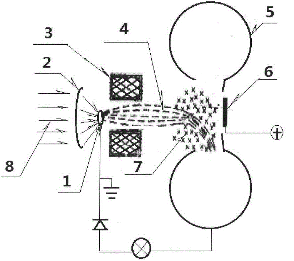
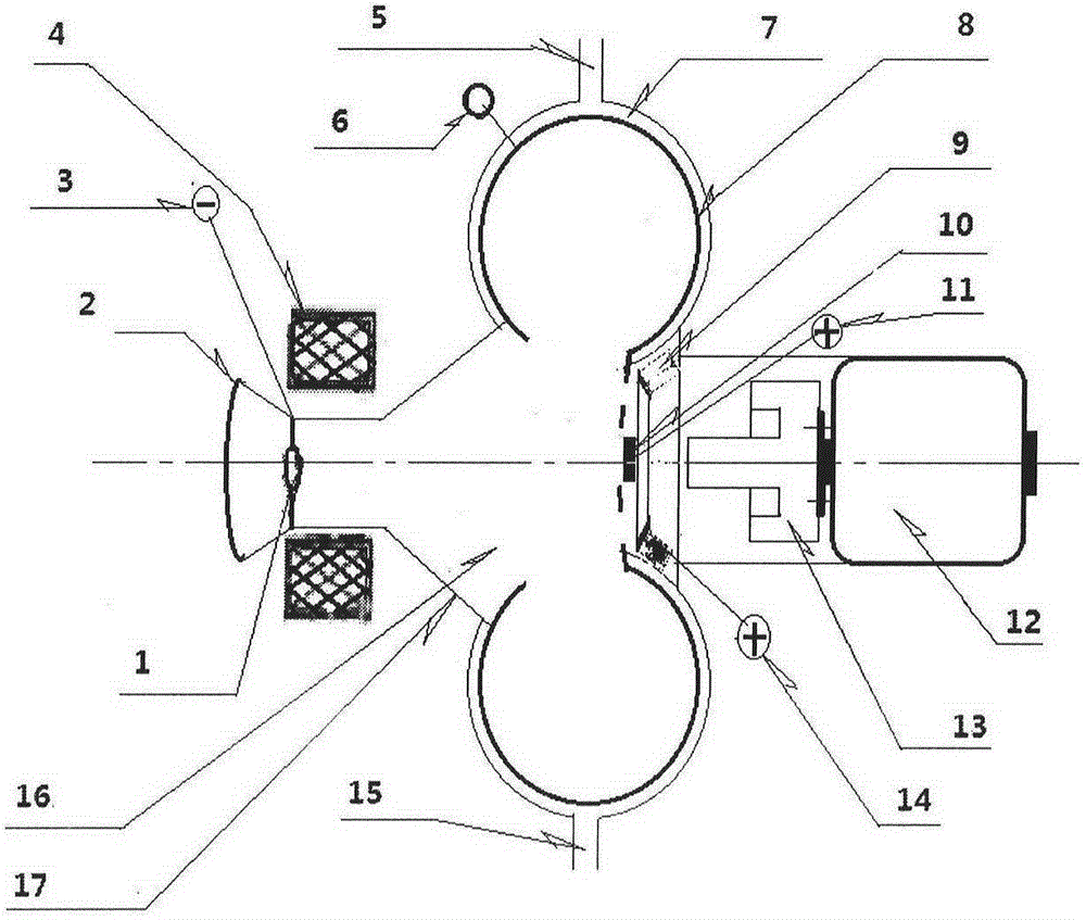
[0032] Figure 6 It is a schematic diagram of solar thermal-field electron emission power generation equipment: Figure 6 Among them, the solar thermal-field electron emission power generation body (1) is installed on the support (3) of the solar cooker (2), and the convex mirror must be aligned with the focus of the solar cooker to form a solar thermal-field electron emission power generation device.

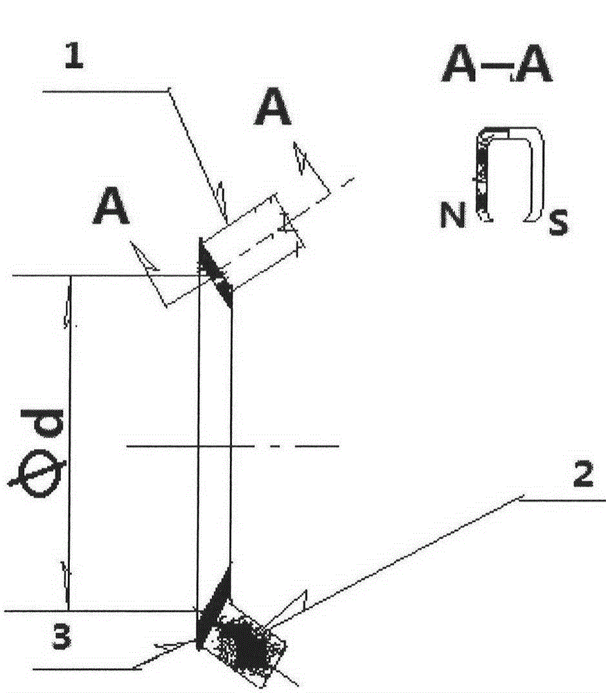
[0033] figure 2It is a schematic diagram of a solar heat-field electron emission generating body: it is composed of a thermal metal (1), a current collector (8), an anode (10), a grid component (9), a special-shaped magnet (13), a motor (12), and a convex mirror (2) and the sealing cover (17) are all assembled with the optical axis of the convex mirror (2) as the center, and are fixed on the sealing cover (17) to form a solar heat-field electron emission generator; the sealing cover (17) is made of temperature-resistant Insulating mater...


PUM


Abstract

The invention relates to a solar thermal-field electron emission power generation device, which comprises a solar cooker and a thermal-field electron emission power generating body. The solar thermal-field electron emission power generation device is characterized in that power generation equipment is formed by mature magnetic focusing and magnetic insulating technologies on the basis of a metal thermal-field electron emission experiment. The solar thermal-field electron emission power generation device has the characteristics of environmental friendliness, low cost and high efficiency, so that the solar thermal-field electron emission power generation device can be widely applied to units and individuals without a public power supply circuit in pasturing, sentry posts, forest protection, offshore aquaculture and the like.

Description

Technical field [0001] The invention relates to a solar heat-field electron emission power generation device, in particular to a solar heat-field electron emission power generation device with magnetic insulation as the main technical feature. Background technique [0002] Worldwide, fossil fuels—coal, oil, and natural gas—are becoming increasingly depleted. However, as reserves in many producing areas decrease, the world is facing sharp fluctuations in energy prices, which impact global economic development. It is necessary to find some energy sources that can guarantee a long-term sufficient supply without causing environmental pollution, so as to alleviate the energy pressure. [0003] Solar energy is both primary energy and renewable energy. It is rich in resources and has no pollution to the environment. Solar photovoltaic power generation is widely used because of its safety, reliability, pollution-free, short construction period, and simple maintenance. But its con...

Claims


Application Information

Patent Timeline
Patent Type & Authority Applications(China)
IPC IPC(8): H02N11/00
CPCY02E10/52H01L31/0543H02S40/22H10N10/00H02S10/30Y02E10/40
Inventor 张国际张逊
Owner 张国际
Why Eureka
Try Eureka