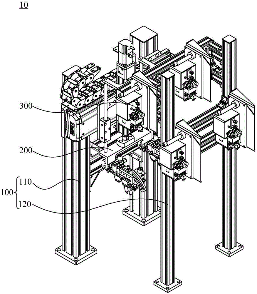
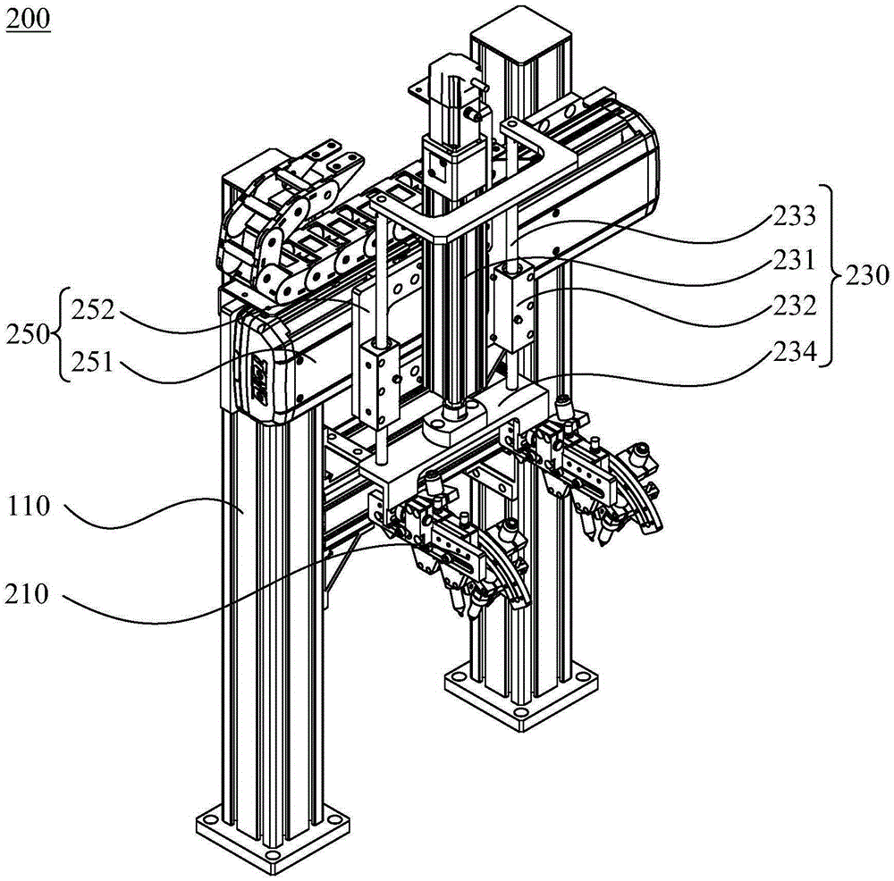
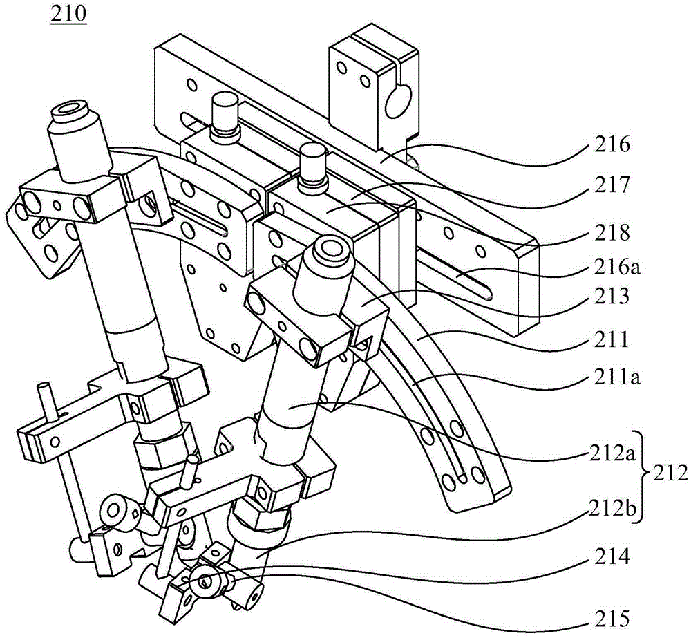
Tin soldering machine

A technology of soldering machine and welding mechanism, which is applied in the direction of tin feeding device, welding equipment, soldering iron, etc., which can solve the problems that soldering equipment cannot be automatically controlled in the production line, high defective rate, and low welding efficiency, so as to improve soldering efficiency and welding quality Effect

Inactive Publication Date: 2016-01-27
SHENZHEN XUANSHUO INTELLIGENT MANUFACTURING TECHNOLOGY CO LTD
View PDF9 Cites 14 Cited by
  • Summary
  • Abstract
  • Description
  • Claims
  • Application Information

AI Technical Summary

Problems solved by technology

[0002] In the existing processing process, for example, in the welding operation of the power cord of the LED bulb lamp and the driver PCB board, manual soldering is often used, which will lead to low welding efficiency, uneven welding quality, and high defective rate. thereby increasing production costs
Moreover, the soldering equipment cannot be combined with the production line to achieve automatic control, and cannot meet the requirements of fully automatic welding in the fully automatic assembly line

Method used


Image

  • Tin soldering machine
  • Tin soldering machine
  • Tin soldering machine

Examples


Embodiment Construction

[0030] In order to facilitate the understanding of the present invention, the present invention will be described more fully below with reference to the associated drawings. Preferred embodiments of the invention are shown in the accompanying drawings. However, the present invention can be embodied in many different forms and is not limited to the embodiments described herein. On the contrary, the purpose of providing these embodiments is to make the disclosure of the present invention more thorough and comprehensive.

[0031] It should be noted that when an element is referred to as being “fixed” to another element, it can be directly on the other element or there can also be an intervening element. When an element is referred to as being "connected to" another element, it can be directly connected to the other element or intervening elements may also be present. The terms "vertical," "horizontal," "left," "right," and similar expressions are used herein for purposes of ill...


PUM


Abstract

The invention relates to a tin soldering machine which comprises a rack, a soldering mechanism and tin wire feeding mechanisms. The soldering mechanism is installed on the rack and comprises electric soldering iron soldering assemblies, a vertical driving assembly and a horizontal driving assembly. The electric soldering iron soldering assemblies can be used for carrying out tin soldering on a workpiece and are installed on the vertical driving assembly. The vertical driving assembly can drive the electric soldering iron soldering assemblies to vertically move. The horizontal driving assembly is installed on the rack, and the vertical driving assembly is installed on the horizontal driving assembly. The horizontal driving assembly can drive the vertical driving assembly to slide horizontally. The tin wire feeding mechanisms are arranged on the rack and used for providing tin wires for the electric soldering iron soldering assemblies. According to the tin soldering machine, automatic tin feeding can be achieved through the tin wire feeding mechanisms, the tin wires and the workpiece can be automatically soldered through the soldering mechanism, the automatic tin soldering process is achieved under the coordination of the soldering mechanism and the tin feeding mechanisms, the tin soldering machine is combined with a production line to achieve automatic control, and the tin soldering efficiency and the soldering quality are improved.

Description

technical field [0001] The invention relates to the technical field of automation equipment, in particular to a soldering machine. Background technique [0002] In the existing processing process, for example, in the welding operation of the power cord of the LED bulb lamp and the drive PCB board, manual soldering is often used, which will lead to low welding efficiency, uneven welding quality, and high defective rate. Thereby increasing the production cost. Moreover, the soldering equipment cannot be combined with the production line to realize automatic control, and cannot meet the requirements of fully automatic welding of the fully automatic assembly line. Contents of the invention [0003] Based on this, it is necessary to provide a soldering machine capable of automatic soldering. [0004] A soldering machine, used for soldering tin wire to a workpiece, comprising: [0005] Frame, welding mechanism and tin wire feeding mechanism; [0006] The welding mechanism is...

Claims


Application Information

Patent Timeline
Patent Type & Authority Applications(China)
IPC IPC(8): B23K3/03B23K3/06B23K101/42
CPCB23K3/03B23K3/063B23K2101/42
Inventor 赵玉涛
Owner SHENZHEN XUANSHUO INTELLIGENT MANUFACTURING TECHNOLOGY CO LTD
Why Eureka
Try Eureka