Clamping mechanism for reinforcing bar mesh welding

A technology of clamping mechanism and steel mesh, which is applied in welding equipment, auxiliary welding equipment, welding/cutting auxiliary equipment, etc., can solve the problems of uneven mesh of steel mesh, large human operation error, and failure to meet the requirements of steel mesh. , to achieve the effect of accurate, rapid and efficient completion of the welding process

Active Publication Date: 2016-01-27
JINAN HUAXIN AUTOMATION ENG
View PDF5 Cites 1 Cited by
  • Summary
  • Abstract
  • Description
  • Claims
  • Application Information

AI Technical Summary

Problems solved by technology

[0002] The use of steel mesh in construction is very common, and with the improvement of building standardization, the requirements for steel bar specifications, sizes and welding quality are getting higher and higher. In the past, steel mesh was mainly welded manually, and the welding efficiency was low. The error of human operation is large, the mesh of the welded steel mesh is uneven, and the quality is poor
Although the existing automatic welding machine has improved the welding efficiency, the degree of standardization is low, the steel bars cannot be accurately positioned, the welding quality is poor, and it cannot meet the standards of steel mesh for construction

Method used


Image

  • Clamping mechanism for reinforcing bar mesh welding
  • Clamping mechanism for reinforcing bar mesh welding
  • Clamping mechanism for reinforcing bar mesh welding

Examples


Embodiment Construction

[0014] The present invention will be described in further detail below with reference to the accompanying drawings and specific embodiments.

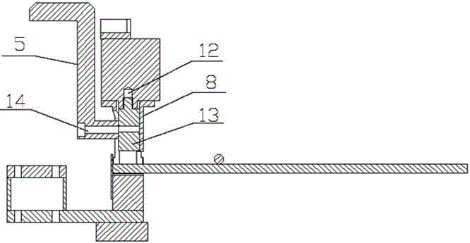
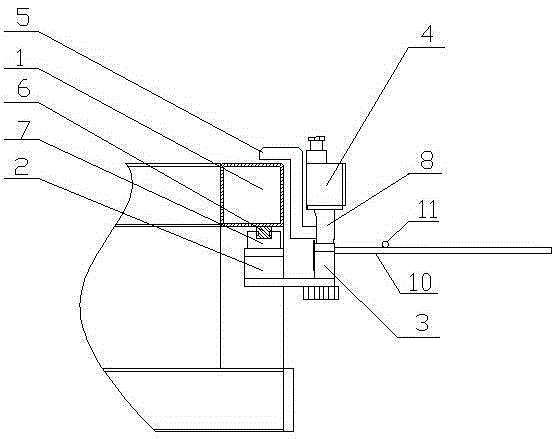
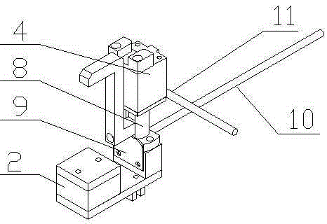
[0015] The accompanying drawing is an embodiment of the present invention. This embodiment includes a clamping base 2 , a lower base 3 , a short-range cylinder 4 and a hook 5 , a sliding block 7 is installed on the clamping base 2 , a linear guide rail 6 is installed on the rebar traction frame 1 , and the sliding block 7 and the linear guide rail are installed on the clamping base 2 . 6 sliding connection; the lower seat 3 is fixed on the clamping seat 2, the front end of the lower seat 3 is provided with a baffle 9, and the vertical steel bar 10 is placed on the upper end of the lower seat 3 to withstand the baffle 9; the upper part of the lower seat 3 is connected by The sleeve 8 is connected with the short-range cylinder 4; the draw hook 5 is movably connected with the reinforcement draw frame 1, and the lower end of the piston rod ...


PUM


Abstract

The invention discloses a clamping mechanism for reinforcing bar mesh welding. The clamping mechanism comprises a clamping base, a lower base, a short-range air cylinder and a drag hook, wherein the clamping base is in sliding connection with a reinforcing bar traction frame; the lower base is fixed on the clamping base; a baffle plate is arranged at the front end of the lower base; one end, on the lower base, of a vertical reinforcing bar abuts against the baffle plate; a position, above the lower base, is connected with the short-range air cylinder through a connecting sleeve; and the drag hook is movably connected with the reinforcing bar traction frame. The clamping mechanism can move the position of a reinforcing bar according to welding dimension requirements and can clamp the reinforcing bar to position, so that the welding quality is prevented from being affected by phenomena such as reinforcing bar sliding and the like in a welding process.

Description

technical field [0001] The invention belongs to the technical field of steel bar welding equipment, and particularly relates to a clamping mechanism for steel bar mesh welding. Background technique [0002] The use of steel mesh in buildings is extremely common, and with the improvement of building standardization, the requirements for steel specifications, dimensions and welding quality are getting higher and higher. In the past, steel mesh was mainly welded manually, and the welding efficiency was low. The human operation error is large, the mesh of welded steel mesh is uneven, and the quality is poor. Although the existing automatic welding machine improves the welding efficiency, the degree of standardization is low, the steel bars cannot be precisely positioned, and the welding quality is poor, which cannot meet the standard of steel mesh for construction. SUMMARY OF THE INVENTION [0003] In order to make up for the deficiencies of the prior art, the present inventi...

Claims


Application Information

Patent Timeline
Patent Type & Authority Applications(China)
IPC IPC(8): B23K37/04B23K101/22
CPCB23K37/0435B23K2101/22
Inventor 赵永文赵厚勇单长正张若虎王春凯孙广田
Owner JINAN HUAXIN AUTOMATION ENG
Why Eureka
Try Eureka