Large-sized optical fiber preform stretching furnace and use method thereof

A technology of optical fiber preform and large size, which is applied in manufacturing tools, glass manufacturing equipment, etc. It can solve the problems of short service life, difficult maintenance, and easy damage of graphite parts, and achieve the effects of good surface, clean environment, and improved life

Active Publication Date: 2016-01-27
JIANGSU HENGTONG PHOTOELECTRIC
View PDF4 Cites 7 Cited by
  • Summary
  • Abstract
  • Description
  • Claims
  • Application Information

AI Technical Summary

Problems solved by technology

[0002] When using the RIC process to produce optical fiber preforms, as the size of optical fiber preforms continues to increase, traditional graphite drawing furnaces cannot meet the requirements for drawing large-sized optical fiber preforms.
When producing large-sized optical fiber preforms, there are problems such as poor surface quality of optical fiber preforms and short service life of graphite parts.
[0003] The patent publication number is CN103663960B, and the title of the invention is "An Optical Fiber Drawing Furnace". A kind of drawing furnace for the downstream of the optical fiber preform is introduced in the invention. The furnace in the invention needs to use a sleeve that runs through the inner cavity of the equipment. In the field of rod manufacturing, there are disadvantages such as easy damage and difficult maintenance

Method used


Image

  • Large-sized optical fiber preform stretching furnace and use method thereof
  • Large-sized optical fiber preform stretching furnace and use method thereof
  • Large-sized optical fiber preform stretching furnace and use method thereof

Examples


Embodiment 1

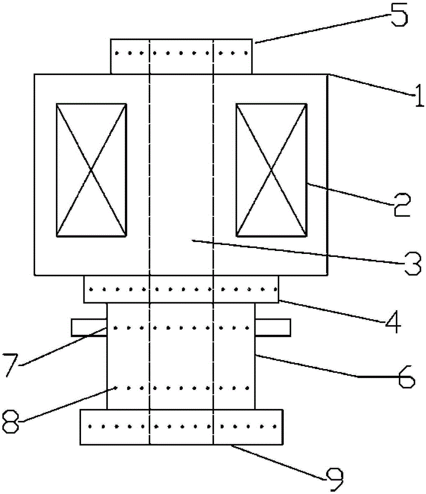
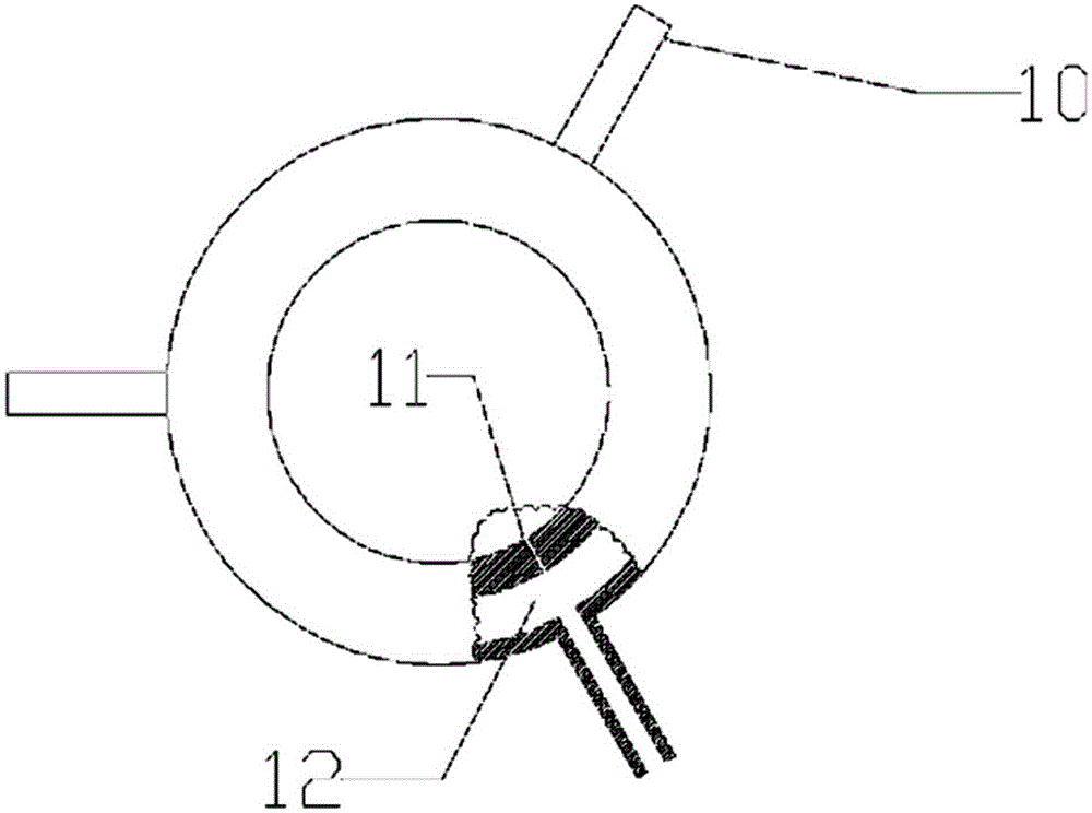
[0033] Such as Figure 1 to Figure 2 As shown, it is a large-scale optical fiber preform drawing furnace according to this embodiment, including: a furnace body 1, a lower sealing device 4 arranged below the furnace body 1, an air purification system 6 in the furnace, and a bottom sealing device. Apparatus 9, wherein an equipment cavity 3 for accommodating the quartz sleeve is formed inside the furnace body 1, and one or more heaters for continuously heating the quartz sleeve are arranged inside the equipment cavity 3 Mechanism 2; the air purification system 6 in the furnace includes a housing, an air extraction system 7 for exhausting exhaust gas, and an air supply system 8 for supplementing sealing gas, and the air extraction system 7 and the air supply system 8 are set On the housing; the equipment cavity 3 communicates with the lower sealing device 4, the furnace air cleaning system 6 and the hollow part of the bottom sealing device 9, and the lower sealing device 4 and / ...

Embodiment 2

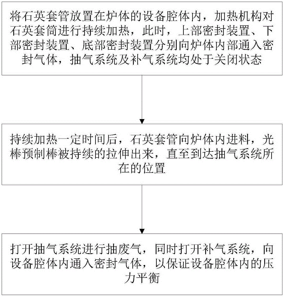
[0041] Such as image 3 As shown, a method for using a large-size optical fiber preform drawing furnace according to this embodiment includes the following steps:

[0042] S1: Place the quartz sleeve in the equipment cavity of the furnace body, and the heating mechanism will continue to heat the quartz sleeve. Both the air system and the air supply system are closed.

[0043] S2: After continuing to heat for a certain period of time, the quartz sleeve is fed into the furnace body, and the light rod preform is continuously stretched out until it reaches the position of the exhaust system.

[0044] S3: Turn on the exhaust system to pump out exhaust gas, and at the same time turn on the air supply system to feed the sealed gas into the equipment cavity to ensure the pressure balance in the equipment cavity.

[0045] Preferably, the step S3 specifically includes:

[0046] Turn on the exhaust system to extract the exhaust gas, the exhaust gas flows into the cavity through the ai...


PUM


Abstract

The invention discloses a large-sized optical fiber preform stretching furnace and a use method thereof. The large-sized optical fiber preform stretching furnace comprises an upper sealing device, a furnace body, and a lower sealing device, an internal air purifying system and a bottom sealing device which are arranged in sequence below the furnace body, wherein a cavity and a heating mechanism are arranged inside the furnace body; an equipment cavity is communicated with hollow parts of the lower sealing device, the internal air purifying system and the bottom sealing device; and the lower sealing device and the bottom sealing device are provided with ventilation holes for introducing sealing gas. Through the arrangement of the bottom sealing device, extended, so that production of large-sized optical fiber preforms can be realized. Moreover, air extraction and air supplement operations can be performed, so that an environment inside the furnace is purified, the service life of a graphite part is prolonged, and the surface quality of the optical fiber preforms is improved. Through use of the graphite part, the service life of the stretching furnace is prolonged by 40 percent compared with an original stretching furnace, the surfaces of the produced optical fiber preforms are in good conditions, and abnormities such as coarseness and surface impurities do not appear.

Description

technical field [0001] The invention relates to the field of optical fiber preform manufacturing, in particular to a large-size optical fiber preform drawing furnace and a method for using the same. Background technique [0002] When using the RIC process to produce optical fiber preforms, as the size of the optical fiber preforms continues to increase, the traditional graphite drawing furnace cannot meet the requirements for drawing large-sized optical fiber preforms. When producing large-size optical fiber preforms, there are problems such as poor surface quality of optical fiber preforms and short service life of graphite parts. [0003] The patent publication number is CN103663960B, and the title of the invention is "An Optical Fiber Drawing Furnace" which introduces a drawing furnace for the downstream of the optical fiber preform. The furnace in the invention needs to use a sleeve that runs through the inner cavity of the equipment. In the field of rod manufacturing, ...

Claims


Application Information

Patent Timeline
Patent Type & Authority Applications(China)
IPC IPC(8): C03B37/012
Inventor 李要飞肖华沈震强陆学刚陈波涛时岩任振华
Owner JIANGSU HENGTONG PHOTOELECTRIC
Why Eureka
Try Eureka