Buffer machine base for absorbing mechanical vibration energy and outputting fluid energy

A technology of energy absorption and mechanical vibration, applied in mechanical equipment, non-rotational vibration suppression, shock absorbers, etc., can solve problems such as the inability to use mechanical kinetic energy reasonably

Inactive Publication Date: 2016-01-27
甘仲光
View PDF6 Cites 0 Cited by
  • Summary
  • Abstract
  • Description
  • Claims
  • Application Information

AI Technical Summary

Problems solved by technology

[0003] The purpose of the present invention is to provide a buffer base that absorbs mechanical vibration energy and outputs fluid energy, so as to solve the problem that the mechanical kinetic energy generated by mechanical vibration cannot be rationally utilized

Method used


Image

  • Buffer machine base for absorbing mechanical vibration energy and outputting fluid energy
  • Buffer machine base for absorbing mechanical vibration energy and outputting fluid energy
  • Buffer machine base for absorbing mechanical vibration energy and outputting fluid energy

Examples


Embodiment 1

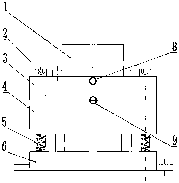
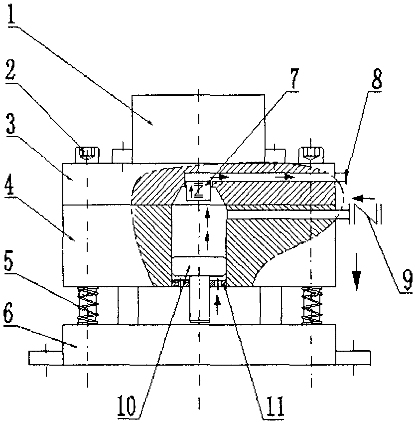
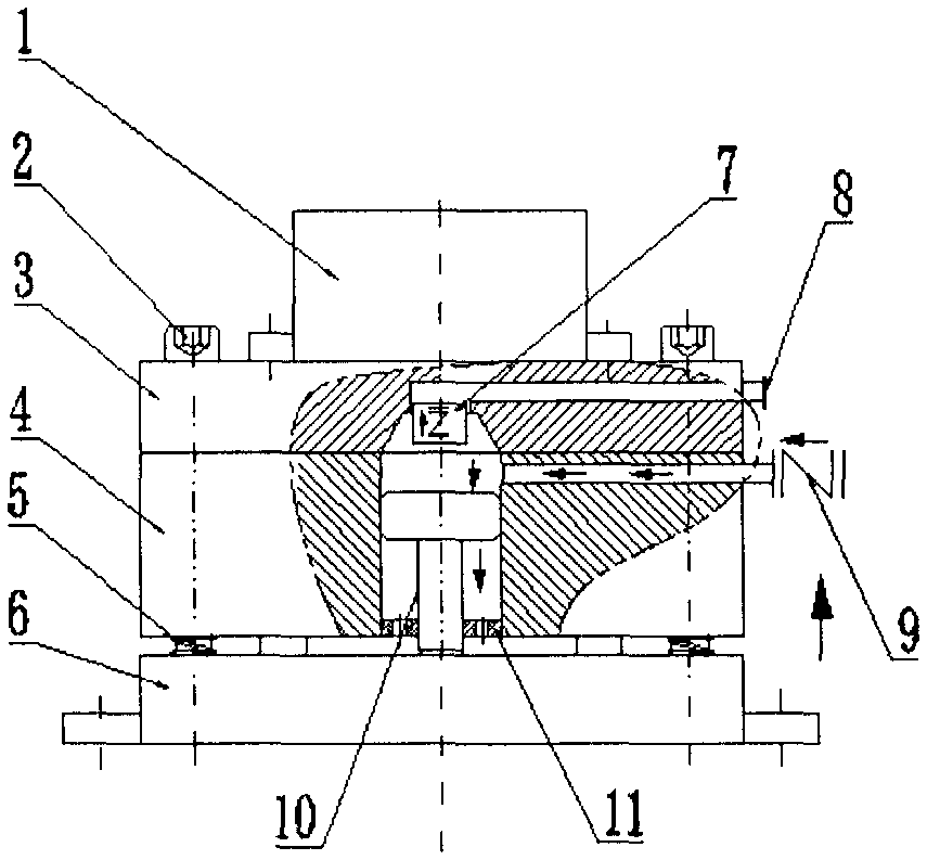
[0012] Embodiment 1: The buffer base includes guide post bolts 2, exhaust integrated board 3, gas production module 4, compression spring 5, support and fixing seat 6, exhaust check valve 7, main exhaust port 8, air intake unit Directional valve 9, piston 10 and diaphragm plate 11; exhaust integrated board 3 and gas production module 4 are connected with support and fixing seat 6 through guide bolt 2, there is a gap between gas production module 4 and support and fixing seat 6, and The guide post bolt 2 at the gap is connected with a compression spring 5, and there is a piston cylinder and a piston on the gas production module 4, and the piston cylinder is connected to the intake check valve 9 through a pipeline; the piston rod of the piston protrudes from the gas production module 4, and It is located between the gas production module 4 and the support and fixing seat 6; there is a diaphragm plate 11 on the gas production module 4 at the piston rod part; there is a cylinder ho...


PUM


Abstract

The invention discloses a buffer machine base for absorbing mechanical vibration energy and outputting fluid energy, and belongs to buffer machine bases for absorbing mechanical vibration energy. The buffer machine base comprises guide column bolts, an exhaust integrated plate, a gas producing module, compression springs, a supporting and fixing seat, an exhaust one-way valve, a main exhaust opening, a gas inlet one-way valve, a piston and a diaphragm plate. The exhaust integrated plate and the gas producing module are connected with the supporting and fixing seat through the guide column bolts. A clearance is arranged between the gas producing module and the supporting and fixing seat, the guide column bolts in the clearance are connected with the compression springs, a piston cylinder and a piston are arranged on the gas producing module, and the piston cylinder is connected with the gas inlet one-way valve through a pipeline. A piston rod of the piston protrudes out of the gas producing module, and is located between the gas producing module and the supporting and fixing seat. The diaphragm plate is arranged at the position, on the piston rod, of the gas producing module. An air cylinder hole corresponding to the piston cylinder is formed in the exhaust integrated plate and communicated with the main exhaust opening, and the exhaust one-way valve (7) is arranged between the air cylinder hole and the main exhaust opening. The buffer machine base has the advantages of achieving transferring, conveying, storage and use of energy.

Description

technical field [0001] The invention relates to a buffer base for absorbing vibration energy, in particular to a buffer base for absorbing mechanical vibration energy and outputting fluid energy. Background technique [0002] At present, many machines or equipment with mechanical action will have mechanical vibration during work. The mechanical vibration is a kind of mechanical kinetic energy. Some mechanical vibration is very unfavorable to the operation of the equipment. In order to eliminate the unfavorable mechanical vibration Vibration, the solution is generally to fix the machine or equipment with mechanical action on a durable machine base, use the ground or the weight of the machine itself to counteract or eliminate the mechanical vibration generated during the operation of the machine, and spend a lot of money to reduce the mechanical vibration The mechanical kinetic energy produced is lost in vain, and the mechanical kinetic energy produced by mechanical vibration ...

Claims


Application Information

Patent Timeline
IPC IPC(8): F16F15/02F16F9/32F16F9/34
Inventor 甘仲光倪鹏邵靖杰
Owner 甘仲光
Why Eureka
Try Eureka