Hydraulic buffering system and equipment comprising hydraulic buffering system

A hydraulic buffer and hydraulic technology, applied in mechanical equipment, fluid pressure actuating devices, springs/shock absorbers, etc., can solve problems such as reducing the energy efficiency of the hydraulic buffer system, and achieve the effect of improving energy utilization efficiency and reducing heat generation.

Active Publication Date: 2016-01-27
BOSCH REXROTH (CHANGZHOU) CO LTD
View PDF6 Cites 3 Cited by
  • Summary
  • Abstract
  • Description
  • Claims
  • Application Information

AI Technical Summary

Problems solved by technology

[0015] However, the current filtering and cooling units need to be equipped with separate pumps to realize the circulation of hydraulic oil, which requires additional energy consumption, which further reduces the energy efficiency of the entire hydraulic buffer system

Method used


Image

  • Hydraulic buffering system and equipment comprising hydraulic buffering system
  • Hydraulic buffering system and equipment comprising hydraulic buffering system
  • Hydraulic buffering system and equipment comprising hydraulic buffering system

Examples


Embodiment Construction

[0033] In the following, some embodiments of the present invention will be described in more detail with reference to the accompanying drawings in order to better understand the basic idea of ​​the present invention.

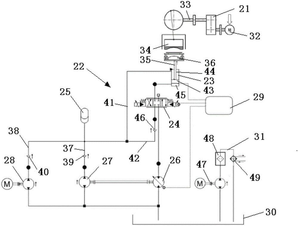
[0034] figure 2 A hydraulic schematic diagram of a hydraulic buffer system 22 used in conjunction with a stamping unit 21 according to an exemplary embodiment of the present invention is shown.

[0035] Such as figure 2 As shown, the hydraulic buffer system 22 includes a hydraulic cylinder 23, a proportional valve 24, an accumulator 25, a hydraulic motor 26, a main pump unit 27, an auxiliary pump unit 28, a motion and force controller 29, an oil tank 30, and a filter and cooling unit 31.

[0036] Such as figure 2 As shown, the stamping unit 21 includes: a motor 32 , a transmission mechanism 33 , an upper mold 34 connected to the transmission mechanism 33 and a lower mold 36 fixed at the top end of the piston rod 35 of the hydraulic cylinder 23 . The rotat...


PUM


Abstract

The invention discloses a hydraulic buffering system. The hydraulic buffering system comprises an oil tank, a hydraulic cylinder suitable for receiving external action force, a main pump unit in hydraulic coupling with the hydraulic cylinder, an auxiliary pump unit, energy accumulators, and a hydraulic motor, wherein the auxiliary pump unit is in hydraulic coupling with the hydraulic cylinder and used for making the hydraulic cylinder be in an initial position to get ready for receiving the external action force when the hydraulic buffering system is started; the energy accumulators are in hydraulic connection with the main pump unit as well as with the auxiliary pump unit and used for accumulating hydraulic oil pressurized by the main pump unit and the auxiliary pump unit; the hydraulic motor is in drive connection with the main pump unit and in hydraulic coupling with the hydraulic cylinder, and when the hydraulic oil in the hydraulic cylinder is squeezed to flow through the hydraulic motor due to the external action force, the hydraulic motor is driven to drive the main pump unit to rotate to fill the energy accumulators. The invention further discloses equipment comprising the hydraulic buffering system. The hydraulic buffering system is high in energy utilization efficiency and capable of reducing the operation cost at the same time.

Description

technical field [0001] The invention relates to a hydraulic buffer system and a device including the hydraulic buffer system. Background technique [0002] The hydraulic buffer system has been widely used in various industrial fields, especially when used in conjunction with the stamping unit, it can give full play to the characteristics of the hydraulic system. [0003] figure 1 It shows a hydraulic schematic diagram of a typical hydraulic buffer system 2 used in conjunction with a stamping unit 1 in the prior art, and the hydraulic buffer system 2 includes: a hydraulic cylinder 3, a proportional valve 4, an accumulator 5, and a main pump unit 6 , filter and cooling unit 7, oil tank 8 and motion and force controller 9. [0004] The working process of the hydraulic buffer system 2 is as follows: [0005] 1) In the initial state, the piston rod 10 of the hydraulic cylinder 3 is lifted to a desired height by means of the main pump unit 6; [0006] 2) State 1: During the st...

Claims


Application Information

Patent Timeline
IPC IPC(8): F16F15/023F15B1/02F15B11/17
Inventor 孙培
Owner BOSCH REXROTH (CHANGZHOU) CO LTD
Why Eureka
Try Eureka